Recent Posts
Under Development: Galvanically Isolated Quad Channel CAN Bus to USB Gateway For Industrial And Automotive Applications
Posted by on
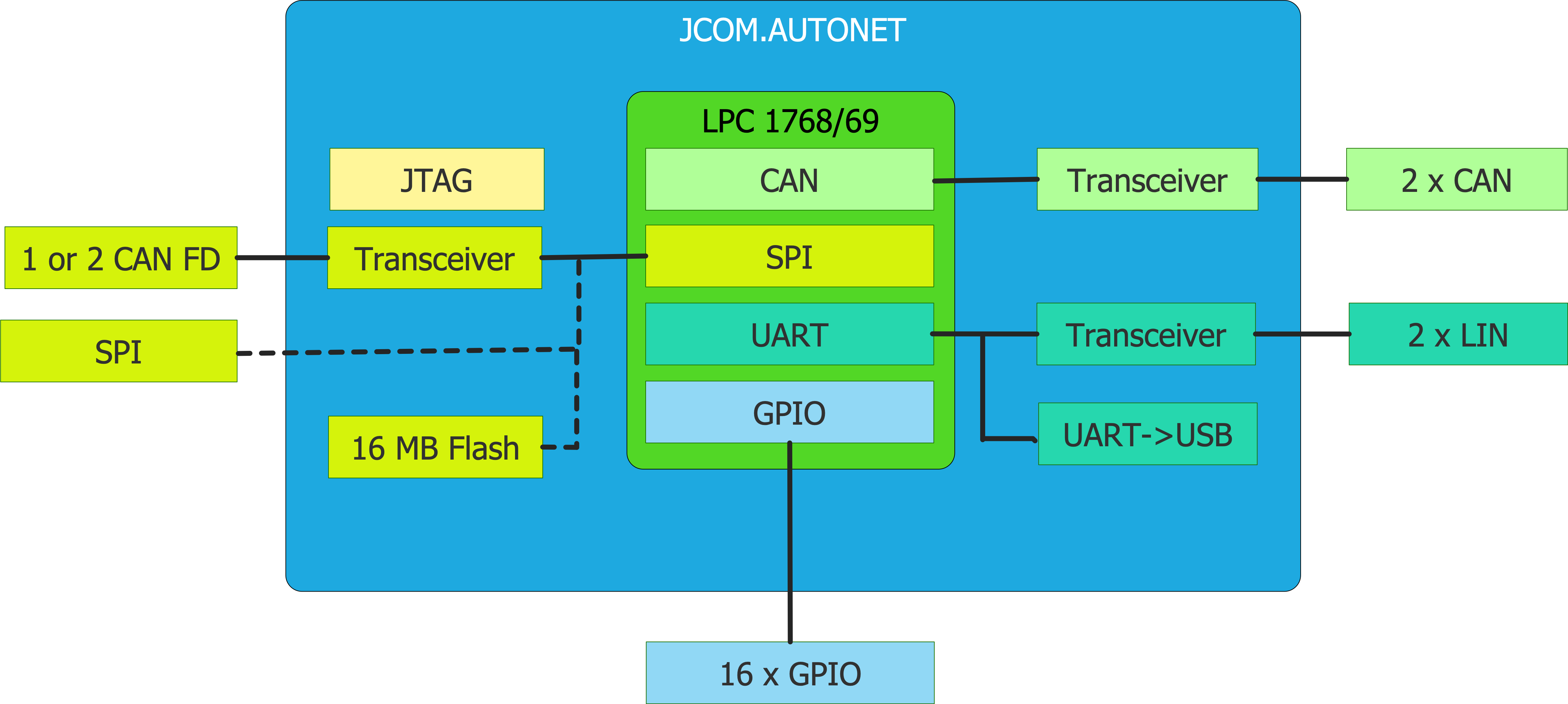
A few months ago, we introduced a development concept for an Automotive Network Development System with CAN, CAN FD, LIN, Ethernet. After further market research plus very much appreciated feedback from customers, we decided to modify the concept and basically create two devices, one for CAN and LIN, the other to CAN and Ethernet. Ethernet, in this case, means not only industrial TCP/IP but also Automotive Ethernet, and putting all these features into one device would require extensive resources.
The decision was made to start with the development of a galvanically isolated four-channel CAN-to-USB gateway board that can also control two LIN Bus ports. The board itself will have two UART ports, which allow the use of external LIN Bus breakout boards, such as our Isolated LIN Bus Breakout Board. In addition, we will be able to support RS 232, RS 485, and RS 422, should the need arise.
A 16 MB flash memory will be used to store communication parameters and firmware features for stand-alone applications, such as a CAN-to-CAN or CAN-to-CAN FD bridges. All in all, the list of possible applications is long:
- Dual CAN to USB Gateway
- Dual CAN FD to USB Gateway
- Quad CAN to USB Gateway (2 x CAN plus 2 x CAN FD)
- CAN to LIN Bus Gateway
- CAN Bridge (Connecting two CAN Bus networks)
- CAN to CAN FD Converter
Add to all these the RS232, RS485, RS422 capabilities as well as integration of an SAE J1939 protocol stack.
As usual, we will create and document a transparent communication protocol, i.e. the data exchange between the gateway board and the host system's USB port - The host can be any system that supports USB, including Windows PC and Linux machines.
We will also create a free-of-charge CAN Analyzing software, similar to our JCOM1939 Monitor Software. The app will support all four CAN ports.
General Features
- Virtually OS independent
- Easily adaptable; just access the COM port
- Works with PCs, Raspberry Pi, BeagleBone, Teensy, Arduino, and other embedded systems
- Serial protocol (CAN to USB and vice versa) is well documented
- C, C# source code available to support customized applications
- Easy firmware updates through USB programming port
- Power applied through USB port or external 7 to 36 VDC
- Operating Range: -40...+85 C
Galvanic Isolation
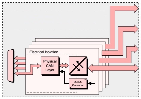
The reading and controlling of multiple CAN Bus connections bares the risk of creating interferences of unpredictable nature. Consequently, we have decided that all CAN channels should be galvanically isolated, not only on the CAN side but also the power supply for each individual power supply as demonstrated in the above picture.
For more information, see: Galvanically Isolated CAN Bus Transceivers Protect Networks Against Destructive Energy...
Real-Time Clock
The onboard Real-Time Clock (RTC) supports CAN Bus message timestamps. However, the firmware will support two timestamps per CAN message frame, the real-time plus time ticks since device powerup. The latter feature will allow the recording and replay of CAN Bus data traffic.
Industrial Strength Design
The gateway board operates within a temperature range of -40...+85 C, making it suitable for operation in harsh environments such as offroad vehicles, etc.
While the board can be powered per USB port, it also accepts an external 7 to 36 VDC power supply. The power supply range covers industrial control voltages (12/24 VDC) as well as diesel engines whose onboard voltage may vary extensively due to engine burden.
Support of More Than Four CAN Channels
The design concept, i.e. conveying the CAN Bus data per USB, opens the door to using multiple boards, thus increasing the number of CAN Bus connections by multiples of four, only limited by the number of USB ports supported by your system.
And, even though the board supports only two CAN FD ports, you can use multiple boards to maintain any number of CAN FD connections. As I pointed out earlier, we will offer several products, initially a Dual CAN, Dual CAN FD, and Quad CAN to USB gateway (2 x CAN plus 2 x CAN FD).
Raspberry Pi Compatibility
The gateway can, of course, also connect to the Raspberry Pi 3/4 with its Linux OS and multiple USB ports, similar to our SAE J1939 board as described in SAE J1939 ECU Simulator And Data Monitor for Raspberry Pi. The gateway board will be designed to fit mechanically onto the RPi, however, without the use of the 40-pin GPIO header, because the only interface needed is a USB port.
Most, if not all, CAN Bus HATs in the marketplace use the RPi's SPI interface, thus limiting the use of other HATS depending on the SPI connection (such as RTCs, Displays, etc.). Our concept is open to expansion, and reading CAN data through the COM port is easy to program (we do deliver C source code to demonstrate the reading and writing of CAN Bus data).
With the support of several gateway boards, the Raspberry Pi could maintain a total of 16 CAN ports, using the onboard four USB interfaces.
Furthermore, the gateway board will be able to power the RPi as well, meaning your RPi design can take advantage of the extended input power range.
Timeline
At the time of this writing we have finished the outlining of the project, the schematics are available, and the PCB design is in the works. A first prototype should be available by mid of November 2020, at which time we will start the firmware development. That being said, the official release is planned for spring of 2021.
For further information, please feel free to contact us.
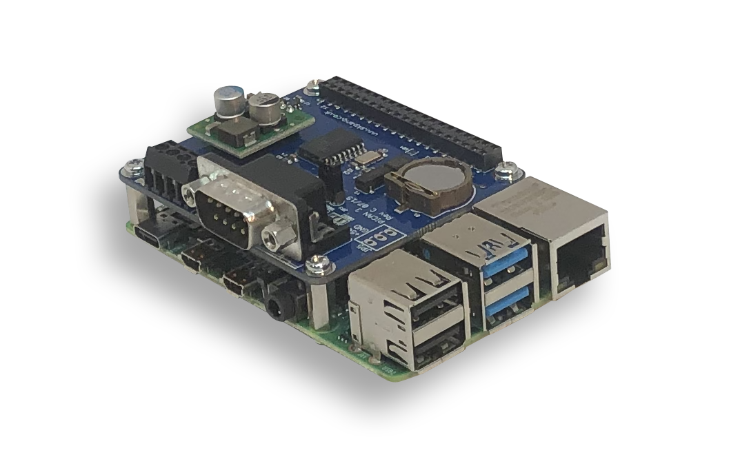
Raspberry Pi 4 With PICAN3 CAN Bus HAT
fThe Raspberry Pi 4 offers groundbreaking improvements in processor speed, multimedia performance, memory, and connectivity compared to the prior-generation boards while preserving backward compatibility. The Raspberry Pi 4 provides desktop performance comparable to entry-level x86 PC systems.
The PiCAN3 board with SMPS (Switch Mode Power Supply) and RTC provides CAN-Bus capabilities for the Raspberry Pi 4. It uses the Microchip MCP2515 CAN controller with MCP2551 CAN transceiver. Connection are made via DB9 or the onboard 3 way screw terminal.
The Switch Mode Power Supply (SMPS) allows connecting an input voltage range of 6 VDC to 20 VDC suitable for industrial and automotive applications and environments. The SMPS will power the Raspberry Pi plus PICAN3.
 Loading... Please wait...


