Blog
Recent Posts
SAE J1939/13 Off-Board Diagnostic Connector Deutsch HD10-9–1939
Posted by on
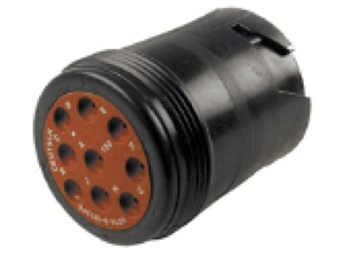
The SAE J1939/13 document defines a standard connector for diagnostic purpose. The connector is a Deutsch HD10 - 9 – 1939 (9 pins, round connector).
According to the document, the connector supports both the twisted shielded pair media (as defined in SAE J1939/11) as well as the twisted unshielded quad media (as defined by ISO 11783-2).
The designations of the individual signal wires are according to the CAN Standard CAN_H and CAN_L. For SAE J1939/11, a third connection for the termination of the shield is denoted by CAN_SHLD.
SAE J1939 Connector Pinout
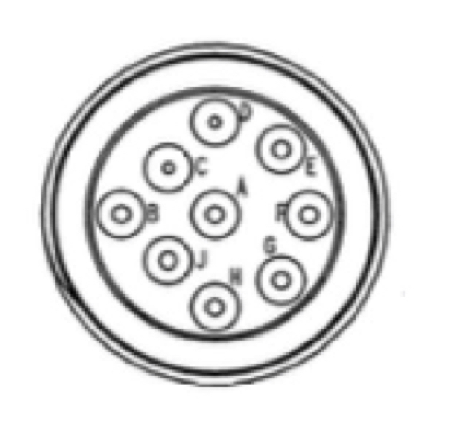
Pin A – Battery (-)
Pin B – Battery (+)
Pin C – CAN_H
Pin D – CAN_L
Pin E – CAN_SHLD
Pin F – SAE J1708 (+)
Pin G – SAE J1708 (-)
Pin H – Proprietary OEM Use or Implement Bus CAN_H
Pin J - Proprietary OEM Use or Implement Bus CAN_L
New Green 9-pin J1939 Connector
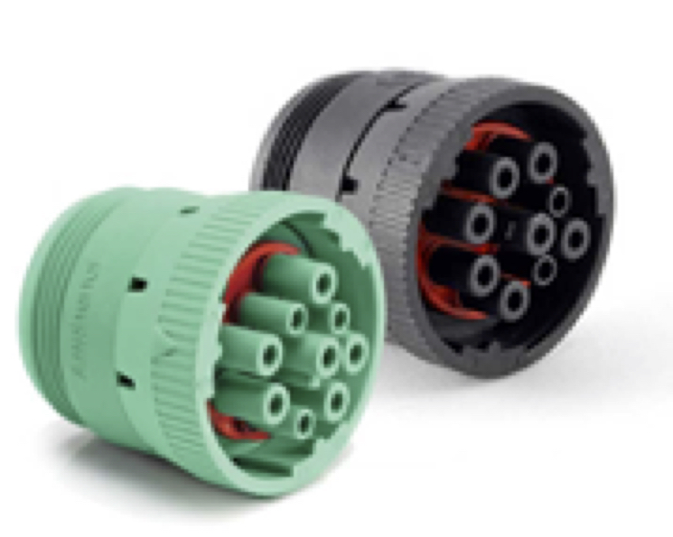
Starting with the model year 2016 and newer trucks, commercial vehicles started showing up with the new green 9-pin plug in the dash. Before, they were black in color, and now they are green. If you have a black cable, you will find that it will not physically fit into the green diagnostic port.
The main reason for the new “green” connector is that not all truck adapters and scanning tools are capable of reading 500 Kbps, and it was feared that technicians would hook up older tools and cause damage to the tool, the truck, or both. The solution was to make the “Green” adapter slightly different so that it works on both the green and black adapter, thus making it backward compatible.
SAE J1939 Starter Kit And Network Simulator
Our J COM.J1939 Starter Kit And Network Simulator is designed to allow the experienced engineer as well as the beginner to experiment with SAE J1939 data communication without the need of connecting to a real-world J1939 network, i.e. a diesel engine. It may sound obvious, but in order to establish a network, you need at least two nodes, and that fact applies especially to CAN/J1939 where the CAN controller will basically shut down after transmitting data without receiving a response. For that reason, our jCOM.J1939 Starter Kit And Network Simulator consists of two J1939 nodes, namely our jCOM.J1939.USB, an SAE J1939 ECU Simulator Board With USB Port.
SAE J1939/13 Off-Board Diagnostic Connector
This post is part of a series on CAN Bus and SAE J1939 Prototyping with the ARM Cortex M3 processor. In order to connect your embedded system to a real vehicle network, you will need to provide the proper wiring and connectors. In the following, I will explain connections as they are used in the industry, but my [...]
 Loading... Please wait...

