 Loading... Please wait...
Blog
Recent Posts
Electronic Logging Device (ELD) - GPS And Real-Time Clock (RTC) Breakout Board For The Arduino Due
Posted by on
 Lately, I had looked into the topic of Electronic Logging Devices (ELD). An ELD is electronic hardware that is attached to a commercial motor vehicle engine to record driving hours. The driving hours of commercial drivers (truck and bus drivers) are regulated by a set of rules known as the hours of service (HOS).
An ELD monitors a vehicle’s engine to capture data on whether the engine is running, whether the vehicle is moving, miles were driven, and duration of engine operation.
In order to develop an ELD you need:
- An embedded system with a powerful processor (such as the Arduino Due) to process the information.
- A CAN Bus (OBD-II or SAE J1939) connection to read the required data (such as our Dual CAN Bus Interface for Arduino Due with extended power range).
- A GPS sensor to determine the vehicle's position.
- A Real-Time Clock (RTC) to mark certain events (such as duty status changes).
The idea behind this design is using the Arduino Due as a basic data gathering and processing device that ultimately transfers the information to an Android-based tablet per Bluetooth connection. The tablet, in turn, displays the information through a sophisticated GUI, and it also handles the transmission of reports per e-mail or text message (which is yet another ELD requirement).
I will address the CAN and Bluetooth connection as well as the Android tablet functionality in another post. Right now, my focus is on integrating a GPS sensor and a Real-Time clock into the Arduino Due.
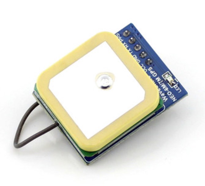
The solution was more than just easy, since I found a very effective breakout module that combines both functions, GPS and RTC, in one board:
Our UART GPS Module With Real-Time Clock features the NEO-7M-C chip onboard, a high-gain active antenna, an IPX interface for connecting different active, external antennas, and a chargeable backup battery, which keeps the ephemeris data when power down and supports hot starts.
Specifications
- TTL level, compatible with 3.3V/5V systems
- Baud rate 9600 only
- Operating voltage: 2.7V-5.0V (VCC input)
- Operating current: 35mA
- TXD/RXD impedance: 510Ω
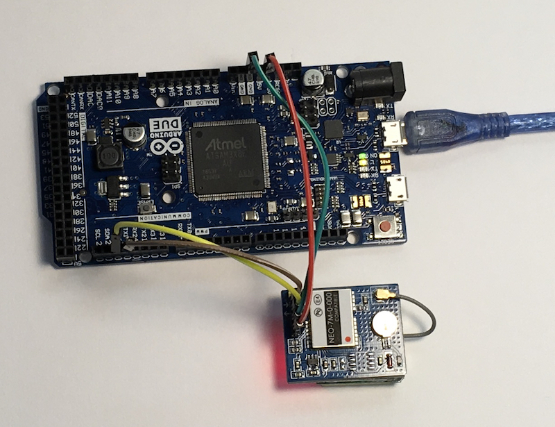
Usage on the Arduino Due
- VCC: connects to 3.3V/5V
- GND: connects to GND
- TXD: connects to RX1
- RXD: connects to TX1
Arduino Due Sketch
Reading and displaying the GPS and Real-Time information is as easy as connecting the breakout board to the Arduino Due. In fact it's so simple that I won't even post the source code for download.
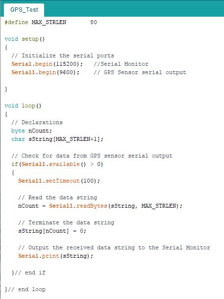
In this example, I am using the RX1/TX1 connection, which is accessed through the Serial1 class. And of course, any of the other serial ports will be as adequate. The result of reading the data is forwarded directly to the Serial Monitor, since the information is entirely in ASCII text:
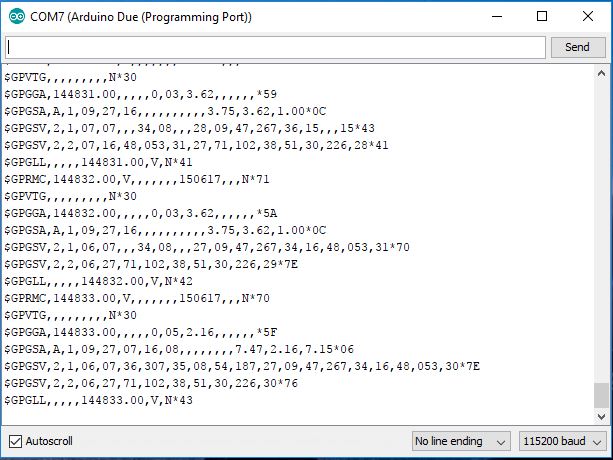
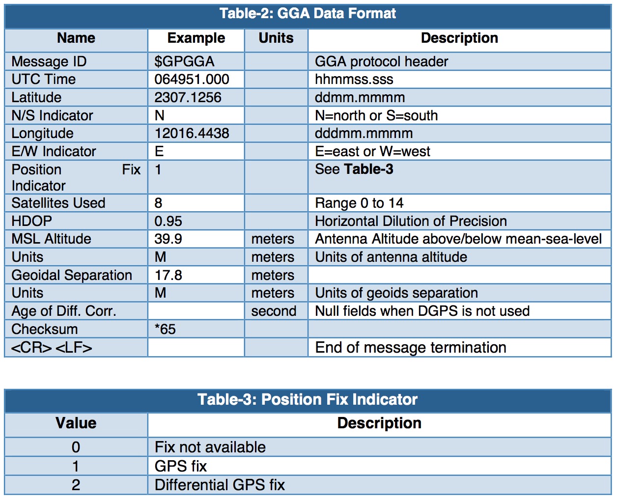
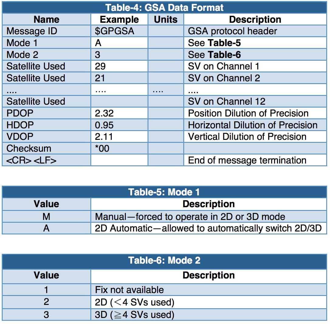
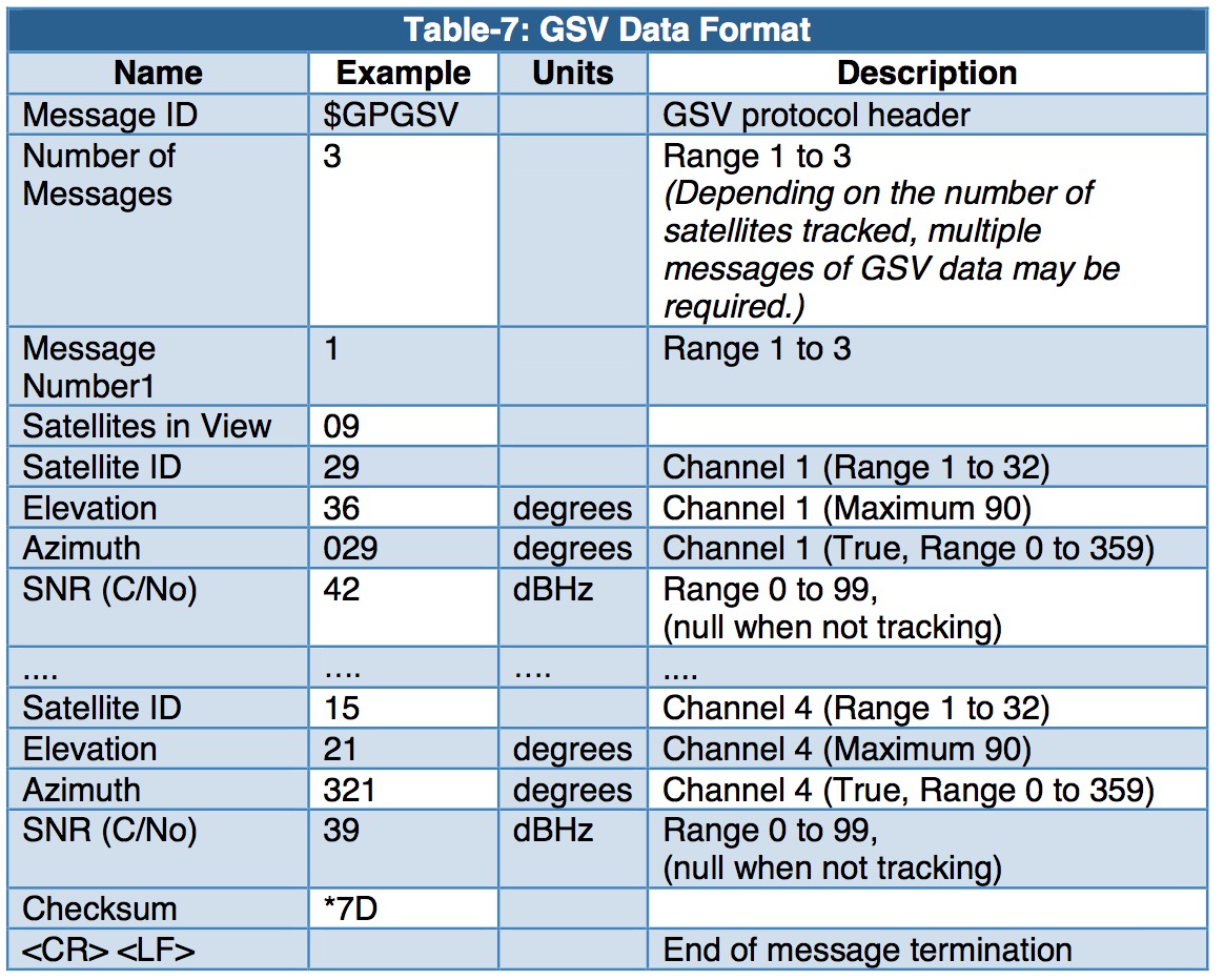
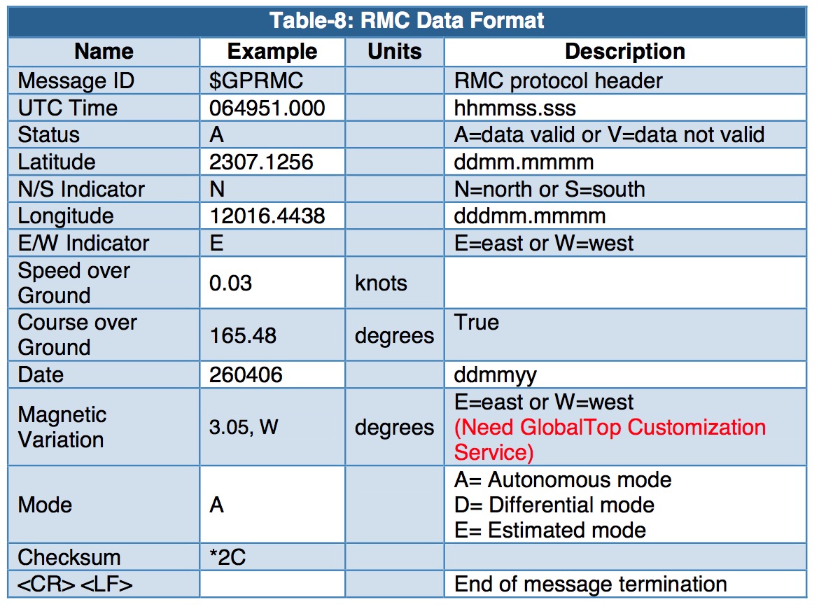
This output, however, is where most of the work lies ahead, i.e. decoding the received the information. This is nevertheless fairly easy to accomplish with the following information, the so-called NMEA output sentences, at hand:
NMEA Output Sentences
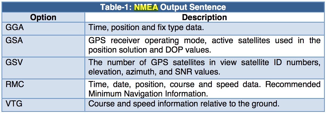
GGA—Global Positioning System Fixed Data. Time, Position and fix related data
GSA—GNSS DOP and Active Satellites
GSV—GNSS Satellites in View
RMC—Recommended Minimum Navigation Information
I have not added code yet that converts the ASCII information into data processed by the Arduino Due. This will be, after all, highly application-specific.