Blog
Recent Posts
Controller Area Network - CAN Bus Message Broadcasting With Data Frames
Posted by on
The following is an excerpt from A Comprehensible Controller Area Network by Wilfried Voss.
The broadcasting of messages in a CAN Bus network is based on a producer-consumer principle. One node, when sending a message, will be the producer while all other nodes are the consumers. All nodes in a CAN Bus network receive the same message at the same time.
In a multi-master network nodes may transmit data at any time. Each node “listens” to the network bus and will receive every transmitted message. The CAN protocol supports message-filtering, i.e. the receiving nodes will only react to data that is relevant to them.
Messages in CAN are not confirmed, because that would unnecessarily increase the bus traffic. CAN assumes that all messages are compliant with the defined standard and if they do not, there will be a corresponding response by all nodes in the network (see Chapter 8.1 - Error Detection). All receiving nodes check the consistency of the received frame and acknowledge the consistency. If the consistency is not acknowledged by any or all nodes in the network, the transmitter of the frame will post an error message to the bus.
If either one or more nodes are unable to decode a message, i.e. either detect an error in the message or are unable to read the message due to an internal malfunction, the entire bus will be notified of the error condition. Nodes that transmit faulty data or nodes that are constantly unable to receive a message correctly remove themselves from the bus (see Chapter 8.3 - Fault Confinement) and thus allow restoration of proper bus conditions.
The CAN Bus standard also defines the request of a transmission from another node by means of a remote frame. The remote frame and the requested data frame use the same message identifier. They are, however, distinguished by the RTR bit (Remote Transmission Request) during the arbitration process (see also Chapter 4 - Message Frame Architecture ).
The following will explain with examples the two methods of message broadcasting, data frame and remote frame broadcasting.
Message Broadcasting With Data Frames
Per definition, CAN Bus nodes are not concerned with information about the system configuration (e.g. node address), hence CAN does not support node IDs. Instead, receivers process messages by means of an acceptance filtering process, which decides whether the received message is relevant for node’s application layer or not. There is no need for the receiver to know the transmitter of the information and vice versa.
All nodes in a CAN Bus network receive the same message at the same time, meaning each node “listens” to the network bus and will receive every transmitted message. The message filter guarantees that the receiving nodes will only react to data that is relevant to them.
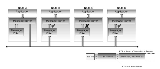
The following picture demonstrates the message broadcasting of a data frame, in this case in a four node CAN network. It also provides a first, but very rudimentary look into the architecture of a CAN Bus controller. Each node represents a CAN controller, which, among many other function blocks, accommodates a programmable message filter and a message buffer.

Note that a data frame is recognized by a dominant RTR (Remote Transmission Request) bit (refer to Chapter 4 - Message Frame Architecture).
The data transmission/reception sequence is as follows (example):
- Node A transmits a message
- Nodes B, C and D receive the message
- Nodes B and D accept the message, Node C declines
This example demonstrates very clearly how flexible the broadcasting of messages can be.
Note: The definition of message IDs and the setup of the message filter depend solely on the application needs. Message IDs must be assigned during the design phase and are usually hard-coded into the application.
Dual CAN Bus Interface For Arduino Due With Extended Power Range
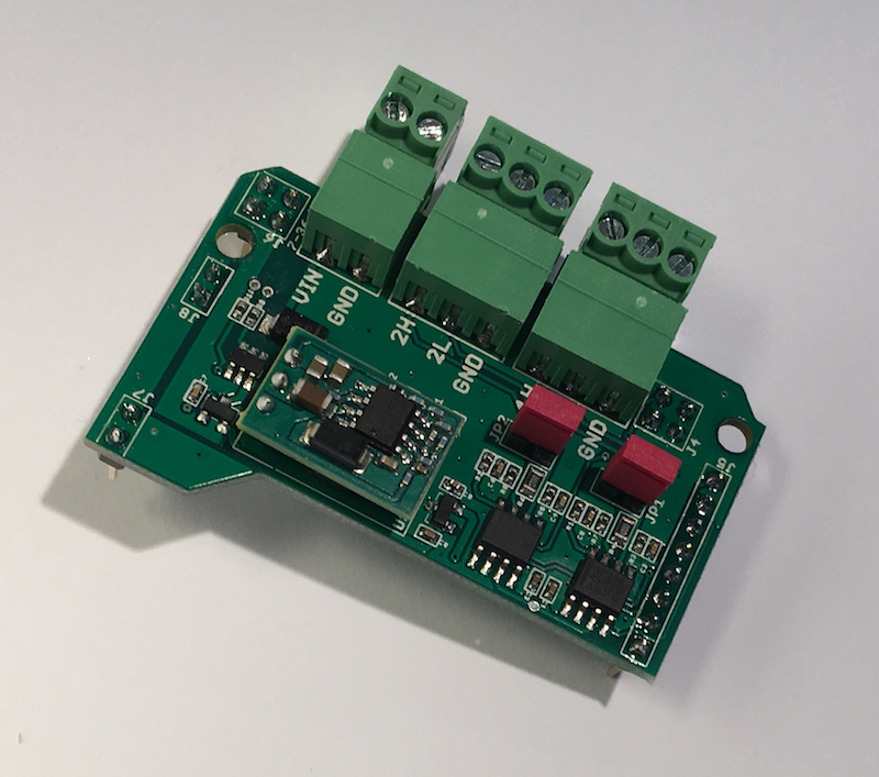
The jCOM.CAN.DUE-X, a dual CAN bus interface for the Arduino Due, is not an Arduino shield in the common sense.
The board incorporates dual CAN transceivers required by the two integrated CAN ports on the Arduino Due while allowing the operation with any Arduino-compatible shield that supports the necessary 3.3 VDC power requirements.
By combining our dual CAN port interface, the Arduino DUE microcontroller, an OBD2 or SAE J1939 cable, and open-source software libraries you are ready to go with powerful a turn-key Arduino-based dual CAN bus solution.
Leverage the 32-bit processing capability of the Arduino DUE plus the built-in CAN ports for your next prototype.
In order to more efficiently serve automotive and industrial applications, the jCOM.CAN.DUE-X board supports an extended input power range of 7 to 36 VDC to power the entire system, i.e. including the Arduino Due itself.
 Loading... Please wait...


