 Loading... Please wait...
Recent Posts
SAE J1939 vs. CAN Bus - What's the Difference?
Posted by on

To say it upfront, the difference between SAE J1939 and CAN Bus (Classical CAN and CAN FD) has all to do with so-called "Higher Later Protocols (HLP)," and SAE J1939 is one of them. I have written a post about HLPs (see: Guide to SAE J1939 - CAN Bus Higher Layer Protocols), but I would like to take a different angle here.
In terms of applications, Classical CAN and CAN FD apply to passenger cars (including OBD-II diagnostics) and small embedded systems.
SAE J1939 applies to diesel engines, primarily for trucks and offroad vehicles, including agricultural equipment using ISOBUS, a derivative of SAE J1939. However, diesel engines apply also to trains, ships, tanks, etc. Another derivative of SAE J1939 is NMEA 2000 for maritime applications.
From a technical standpoint, I will start with the ISO/OSI 7-Layer Model, as demonstrated in the following image. Without going into all details, it is apparent that the CAN Bus technology bypasses several layers that are mandatory for network management.
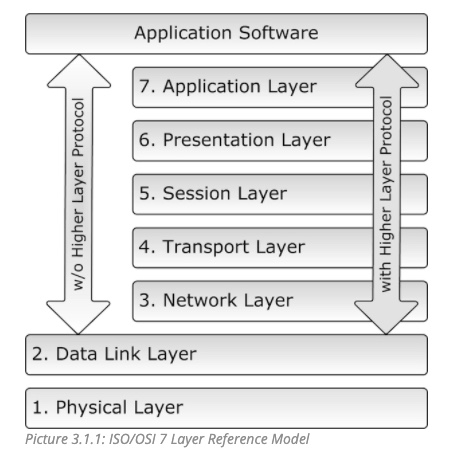
However, that is not necessarily a disadvantage since this circumstance allows the CAN Bus to operate at a low cost and with minimum software resources at high performance as required for numerous embedded applications. Nevertheless, bypassing these layers results in a few restrictions.
The CAN Bus technology does not support node IDs. Instead, CAN focuses on message IDs, meaning each node in the network must know exactly which message ID it needs to read or transmit without caring where it came from or where it goes. It may appear restrictive, but it saves plenty of software resources. On the other hand, it requires good housekeeping of message IDs. Consequently, the CAN Standard does not allow two or more nodes to transmit the same message ID because a message collision could result in unforeseen consequences. However, while the CAN Standard ISO 11898 strictly forbids the use of identical message IDs, it does not address how it handles a violation of the rule.
Classical CAN is limited to eight bytes per data frame, while CAN FD can hold up to 64 bytes. However, the use of CAN FD for SAE J1939 is questionable, specifically for legacy applications, since Classical CAN and CAN FD cannot share the same bus. There are activities to incorporate CAN FD into SAE J1939, but I wouldn't hold my breath at this time.
SAE J1939 represents a very ingeniously designed protocol, which uses Classical CAN as its hardware layer. SAE J1939 adds software resources on top of Classical CAN to implement network management, including node IDs, address claim procedure, message lengths of up to 1785 bytes, and more.
Note: The SAE J1939 Standard consists of several documents indexed from SAE J1939-1x to SAE J1939-7x in reference to the ISO/OSI 7-Layer Model.
SAE J1939 is a prime example of good American engineering according to the KISS principle (KISS = Keep It Simple, Stupid!). Consequently, SAE J1939 is more effective (higher bandwidth) than other higher layer protocols such as CANopen or DeviceNet.

SAE J1939 Gateway Module with USB Port, RTC, MicroSD Memory Card
The JCOM.J1939.USB processor board is a high-performance, low-latency vehicle network adapter for SAE J1939 applications. It allows any host device with a USB COM port to monitor SAE J1939 data traffic and communicate with the SAE J1939 vehicle network.
The board supports the full SAE J1939 protocol according to J1939/81 Network Management (Address Claiming) and J1939/21 Transport Protocol (TP). In addition, an extensive programming interface supports Windows and Linux/Ubuntu applications, including complete C/C++/C# source code for short time-to-market developments.
The board's strength lies in the fact that the entire SAE J1939 protocol, including all timing requirements, is stored on-chip, thus taking the burden off the central system (PC). The board uses a USB COM port to communicate with the main system, i.e., all data transfer is handled through a standard COM port access. The communication protocol between the board and the primary system is well documented and thus allows porting to any computer system with a USB connection. Working source code libraries exist for Windows (C# under Visual Studio 2102/2013), Linux and its derivatives (C++ using Code::Blocks), and Raspberry Pi (C using the standard gcc compiler).