 Loading... Please wait...
Recent Posts
SAE J1939 Programming with Arduino - Receiving J1939 Message Frames
Posted by on
This post is part of a series about SAE J1939 ECU Programming & Vehicle Bus Simulation with Arduino.

This Arduino project provided a bit of a challenge after I had forgotten my own advice.
Note: In order to test a CAN/J1939 application, you need at least two CAN/J1939 nodes to establish a network communication. The second node can be another Arduino with CAN shield or (if the budget allows) another CAN/J1939 device with CAN/J1939 data monitoring capabilities.
In other words, in order to receive J1939 messages, I needed a transmitter. However, the solution was simple: I used a second Arduino with CAN shield and ran the application as described in chapter SAE J1939 Simulation Example, in this case the advanced version.
In order to receive and transmit J1939 message frames in a more comprehensive way (rather than receiving mere CAN Bus messages that involve decoding the message ID), I added more J1939 functionality to the can.cpp module.
The new (or modified) function calls are:
- j1939Transmit – This function call (which we already used in the previous project) now supports the setting of source and destination address – the previous version allowed only the source address and thus did not directly support peer-to-peer communication.
- J1939Receive – This function’s parameters are very similar to those as used with j1939Transmit with the difference that the parameters are pointers to variables, because these are parameters we receive.
- canReceive – This function (called by j1939Receive) has been extended to use a CAN message ring buffer in order to prevent timing problems and, consequently, avoid the loss of messages.
- J1939PeerToPeer – This function (called by both, j1939Transmit and j1939Receive) determines whether or not the passed PGN represents a peer-to-peer (direct node) communication. If yes, the function will insert the destination address into the CAN Bus message ID.
The actual loop() function is fairly simple, since most of the code is used to display the received J1939 data frame.
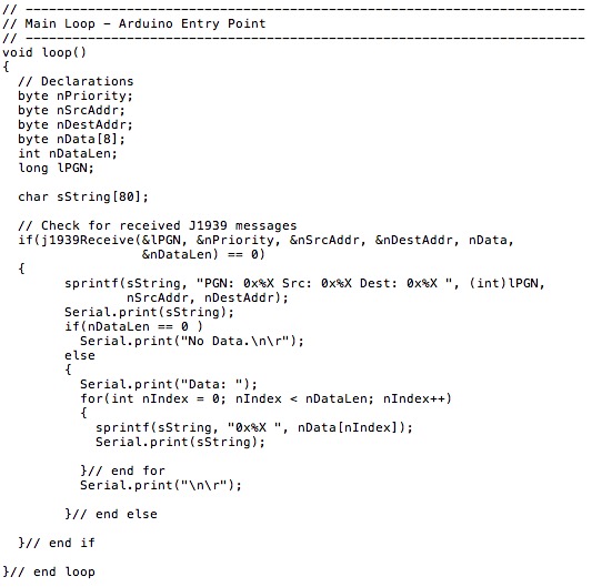
Note: This Arduino project is available through the download page at ARD1939 - SAE J1939 Protocol Stack for Aduino.
The data is being displayed on the Arduino’s Serial Monitor, and the result is as expected (for demonstration purposes, I have highlighted PGN 0xFEF3, which appears every five seconds).
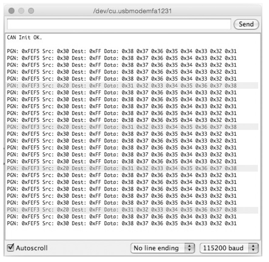
Note: The destination address is being displayed as 0xFF (255), which is the global address, meaning that both PGNs are broadcast messages.

SAE J1939 has become the accepted industry standard and the vehicle network technology of choice for off-highway machines in applications such as construction, material handling, and forestry machines. J1939 is a higher-layer protocol based on Controller Area Network (CAN). It provides serial data communications between microprocessor systems (also called Electronic Control Units - ECU) in any kind of heavy duty vehicles. The messages exchanged between these units can be data such as vehicle road speed, torque control message from the transmission to the engine, oil temperature, and many more.
A Comprehensible Guide to J1939 is the first work on J1939 besides the SAE J1939 standards collection. It provides profound information on the J1939 message format and network management combined with a high level of readability.