 Loading... Please wait...
Recent Posts
SAE J1939 Data Monitoring And Simulation With The Arduino
Posted by on

The following is an excerpt from SAE J1939 ECU Programming & Vehicle Bus Simulation with Arduino by Wilfried Voss
In general, there are three different intentions for connecting to a J1939 vehicle network:
- Mere monitoring, processing, and display of network data traffic.
- All functions as described under 1. but extended by the ability of sending data into the J1939 bus.
- All functions as described under 1. and 2. but extended by the J1939 Transport Protocol, supporting messages with more than 8 data bytes.
Let's address these three approaches:
- The mere monitoring, processing, and display of network data traffic does not require any network management functionality (i.e. the actual SAE J1939 protocol). Simply connect your monitoring device to the vehicle bus and filter those messages relevant to your needs.
- The ability of sending or requesting data to/from the J1939 bus requires that your system (ECU = Electronic Control Unit) owns an 8-bit address. Since addresses in a J1939 vehicle network are dynamic (i.e. they may change after each power-up), your system must follow the J1939 Address Claiming Procedure according to SAE J1939/81.
- The J1939 Transport Protocol (SAE J1939/21) is that particular part of the network management functionality that raises the level of complexity. However, the vast majority of J1939 applications do not require the Transport Protocol (TP). The TP is mostly used for non-critical, data-intensive communication tasks.
The following chapter is about J1939 monitoring and simulation projects, which do not require a J1939 protocol implementation. A later chapter will introduce the ARD1939 protocol stack, allowing full communication with a J1939 vehicle network.
SAE J1939 Monitoring And Simulation
As I wrote before, both versions of the Arduino used in this book, the Uno and the Mega 2560, are well suitable for SAE J1939 monitoring and simulation projects. Until now, the simulation of J1939 data traffic involved the purchase of expensive simulation devices and the associated steep learning curves. All this changes with the Arduino’s easy-to-use hardware and software solutions.
Writing J1939 monitoring and simulation examples for the Arduino is a matter of a few hours or even less when using the following programming samples as a template.
Note: All Arduino projects (Sketches) as introduced in the following will use the Serial Monitor at a baud rate of 115,200 bit/sec (See also my remarks in chapter “Serial Interface And CAN Timing Considerations”).
SAE J1939 Simulation Example
The following programming sample demonstrates effectively how easy simulating SAE J1939 data traffic can be (while the level of complexity can be easily adjusted to the application requirements).
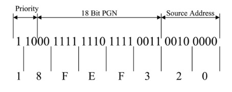
However, before we dive into the actual coding, we need to design the simulated messages, i.e. we need to determine the CAN 29-Bit message ID, which includes the actual PGN, the PGN’s priority, and the application’s source address.
Message Design
For this programming sample I have randomly chosen two PGNs from the vast selection of available parameter group numbers. They are:
- PGN 65267 – Vehicle Position, provides the vehicle’s latitude and longitude.
- Transmission Repetition Rate: 5 sec
- Parameter Group Number: 0xFEF3
- Data Length: 8 bytes
- Default Priority: 6
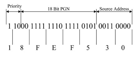
- PGN 65269 – Ambient Conditions, provides barometric pressure, cab interior temperature, ambient air temperature, engine air inlet temperature, and road surface temperature.
- Transmission Repetition Rate: 1 sec
- Parameter Group Number: 0xFEF5
- Data Length: 8 bytes
- Default Priority: 6
Note: In order to implement other or further PGNs, you will need a copy of the SAE J1939/71 standard for a detailed description of the parameters and their data format. You may find some of them by browsing the Internet, but be aware that there is no complete online reference. A description of all PGNs is out of the scope of this book.
Besides the actual PGNs, we will also need to simulate the application’s source address. The source address is usually determined through the address claim process of the SAE J1939 protocol stack, which is not yet part of this programming sample.
For mere test and demonstration purposes, it is sufficient to assume the addresses. In the following, we use 0x20 for PGN 65267 and 0x30 for PGN 65269.
Applying the PGNs plus priority plus source address, the message IDs are:
- PGN 65267 – Vehicle Position: 0x18FEF320
- PGN 65269 – Ambient Conditions: 0x18FEF530
Arduino Code
The Arduino code is quite simple and virtually self-explanatory. However, let me lose a few words on the program’s structure.
First of all, depending on the CAN shield used for this programming sample, please make sure you set the proper CS (Chip Select) for the CAN controller as described in module can.cpp (See also my remarks in the chapter about the CAN-BUS Shield by Seeed Studio).
In the main program module J1939_Data_Traffic_simulation I defined two messages, msgVehiclePosition and msgAmbientConditons, and filled them with random data.
In the main loop I use the delay function to create a one-second timer by means of the variable nCounter. The content of nCounter triggers the transmission of the corresponding messages.
The actual program code is fairly simple:

Note: This Arduino project is available through the download page at http://ard1939.com.

Arduino-Based ECU Development Board With Dual CAN Bus Interface
Leverage the power of an ARM Cortex M3 32-bit processing capability combined with a dual CAN Bus interface to create your next CAN Bus or SAE J1939 application or prototype. By combining our dual CAN port interface, the Arduino DUE microcontroller, an OBD2 or SAE J1939 cable, and open-source software libraries, you are ready to go with a powerful turn-key Arduino-based dual CAN bus solution.
Use the vast resources of Arduino software (sketches) and hardware components (shields) to create your CAN Bus, OBD2, or SAE J1939 application.