Recent Posts
Programming Thomson Electrac Linear Actuator - Sleep Mode
Posted by on
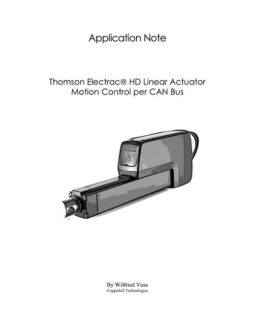
This post represents an excerpt of Thomson Electrac HD Linear Actuator Motion Control per CAN Bus. The application note is available in eBook and Kindle format, and it includes a free downloadable source code. More Information...
In this post, I am explaining the actuator's sleep mode, which, if not fully understood, may cause some headache during the development process.
Thomson Electrac Linear Actuator - Sleep Mode
The Electrac HD utilizes a sleep mode operation when positioning is no longer required. This feature allows for a constant battery connection with minimal drain while the engine or vehicle is not running. After five seconds of bus inactivity, the actuator will put itself to sleep. The actuator will begin a wake-up phase when bus activity is restored, followed by an address claim request.
Note: The Sleep Mode posts a major challenge for advanced motion control applications when it is not fully understood (because its side effects are not fully documented). In the following, I will try to address these quirks – my apologies for the lengthy description but I would have been happy to have the information when I started the project.
The Sleep Mode does have some impact on the programming. If the actuator goes into sleep mode, it will cease sending feedback messages, and it will take several hundreds of milliseconds before it detects a software start signal. As documented in the user manual, “the actuator will begin a wake-up phase, followed by an address claim request.” This behavior may not impact all applications, but it is important to be aware of the consequences.
In detail, the actuator requires at least one start signal transmitted per Actuator Control Message (ACM) after address claim to start motion until the desired position is reached, meaning it takes in average three ACMs to start motion after the actuator “wakes up.” The first ACM wakes the actuator up. The actuator sends the address claim message and waits for a possible address challenge, which does not occur when the setup contains merely the actuator and the control unit. The second ACM is usually ignored since it occurs during the address claim timeout. The third ACM, e.g., representing the start signal, will be recognized.
Note: The Address Claim message provides a minimum but incomplete compliance with the SAE J1939 Standard. The purpose is to prevent address collisions within the network, i.e., two nodes can negotiate who keeps their initial address and who needs to determine a new address. The user manual does not refer to a scenario where the actuator’s address is challenged. My assumption is that an address conflict is not solved. Overall, in my experience, the Address Claim message, in its current form, is useless, and it is being ignored in my code.
Another effect is that, during that wakeup period, the actuator reports a Motion Complete status within the Actuator Feedback Message (AFM). The AFM is transmitted as a response to the ACM message. In detail, after “wake-up,” the actuator reports Motion Flag = 0 (i.e., motion completed) for about three to four data frames.
The result is, despite receiving a Motion Start signal per ACM, the actuator initially reports the motion as completed, which defies common logic thinking.
Note: All described scenarios in this section are due to my observations; they are not documented in the user manual. Initially, I sent only one ACM to start a motion cycle but encountered problems, i.e., the actuator did not move. Consequently, in our demo program, I send ACMs periodically, i.e., every 100ms (actually, as recommended in the user manual, however, without explanation why).
In my program, I went so far as to detect whether the actuator was in Sleep Mode, followed by a “wake up” command when necessary. For some applications, this may be considered overkill, but it made the actuator’s “state of mind” more predictable.
In general, I strongly recommend that you consider if and how your application needs the sleep mode feature. The Sleep Mode is supposed to conserve energy when batteries are used.
The Sleep Mode also has some major, even disruptive impact when you need to control more than one actuator.
If you need sleep mode, never ever connect two or more actuators in the same network (see chapter Multiple Actuators in the Same Network). Keep each actuator in its own network (control loop), i.e., isolated from any other CAN data traffic. Any data traffic, even that not associated with the actuator, will keep the actuator awake.
Arduino-Based ECU Development Board With Dual CAN Bus Interface
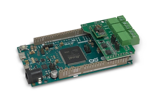
Leverage the power of an ARM Cortex M3 32-bit processing capability in combination with a dual CAN Bus interface to create your next CAN Bus or SAE J1939 application or prototype. By combining our dual CAN port interface, the Arduino DUE microcontroller, an OBD2 or SAE J1939 cable, and open-source software libraries you are ready to go with powerful a turn-key Arduino-based dual CAN bus solution.
 Loading... Please wait...


