 Loading... Please wait...
Recent Posts
jBoard-X2 - Hardware Installation For SAE J1939 Data Monitor, Analyzer, ECU Simulator
Posted by on

This post describes the installation and connection of the Copperhill SAE J1939 Data Monitor, Analyzer, ECU Simulator With jBoard-X2.
This is the perfect tool to monitor, analyze, and simulate SAE J1939 data traffic. The system combines our industrial-strength jBoard-X2 that functions as an SAE J1939 to USB gateway. A comprehensive and easy-to-use, easy-to-understand Windows software displays not only SAE J1939 data traffic; it also allows to scan the network, simulate an ECU (incl. full node address negotiation features), and respond to data request messages.
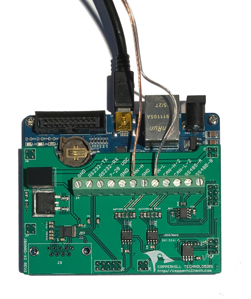
Basically, there are only few connections to establish, the power supply, the USB port, and the CAN interface.
Power Supply
In order to supply power to the jBoard-X2, there are three options:
- A 5 VDC power supply (provided in the scope of delivery).
- An external 7 to 28 VDC power supply.
- The USB connection.
The USB connection is the most convenient way to apply power to the jBoard-X2, but this option is only recommended when using a desktop computer or, in case you want to use a laptop, a USB hub with external power supply. Powering the jBoard-X2 directly through a laptop's USB port may result in communications and power problems. This is, however, highly system-dependent.
The external 7 to 28 VDC power supply may apply in case you want to power the board through a vehicle's power system (Battery, Alternator). The power connection is available through the onboard terminal block; the connections are marked as GND and 7 - 28 VDC.
USB Port
The jBoard-X2 provides two USB ports, and the board can be powered through either one. However, the communication to the Windows PC is managed through CN7, which is the USB port right next to the Ethernet port (as indicated in the image above). Most modern Windows computers will already support this USB port without any tedious driver installation (that's the reason why we chose it over the other one), otherwise please refer to the product page for further information.
CAN Bus Connection
The CAN Bus connection is provided through the onboard terminal block, connections CAN-H and CAN-L.
SAE J1939/13 Off-Board Diagnostic Connector
J1939/13 defines a standard connector for diagnostic purpose. It does allow access to the vehicle communication links. The connector is a Deutsch HD10 - 9 – 1939 (9 pins, round connector).
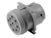
According to the official document, SAE J1939/13 Off-Board Diagnostics Connector, the connector supports both the twisted shielded pair media (as defined in SAE J1939/11) as well as the twisted unshielded quad media (as defined by ISO 11783-2). The designations of the individual signal wires are according to the CAN Standard CAN_H and CAN_L. For SAE J1939/11, a third connection for the termination of the shield is denoted by CAN_SHLD.
The pin assignment is as follows:
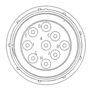
Pin A – Battery (-)
Pin B – Battery (+)
Pin C – CAN_H
Pin D – CAN_L
Pin E – CAN_SHLD
Pin F – SAE J1708 (+)
Pin G – SAE J1708 (-)
Pin H – Proprietary OEM Use or Implement Bus CAN_H
Pin J - Proprietary OEM Use or Implement Bus CAN_L
For more detailed information on the connector and its wiring, please refer to the official SAE document.
A Comprehensible Guide to J1939

SAE J1939 has become the accepted industry standard and the vehicle network technology of choice for off-highway machines in applications such as construction, material handling, and forestry machines. J1939 is a higher-layer protocol based on Controller Area Network (CAN). It provides serial data communications between microprocessor systems (also called Electronic Control Units - ECU) in any kind of heavy duty vehicles. The messages exchanged between these units can be data such as vehicle road speed, torque control message from the transmission to the engine, oil temperature, and many more.
The information in this book is based on two documents of the SAE J1939 Standards Collection: J1939/21 - Data Link Layer J1939/81 - Network Management A Comprehensible Guide to J1939 is the first work on J1939 besides the SAE J1939 standards collection. It provides profound information on the J1939 message format and network management combined with a high level of readability.
=> Read More...