Loading... Please wait...
Recent Posts
How To Build A GPS To USB Interface, Including A Real-Time Clock, Within Minutes
Posted by on
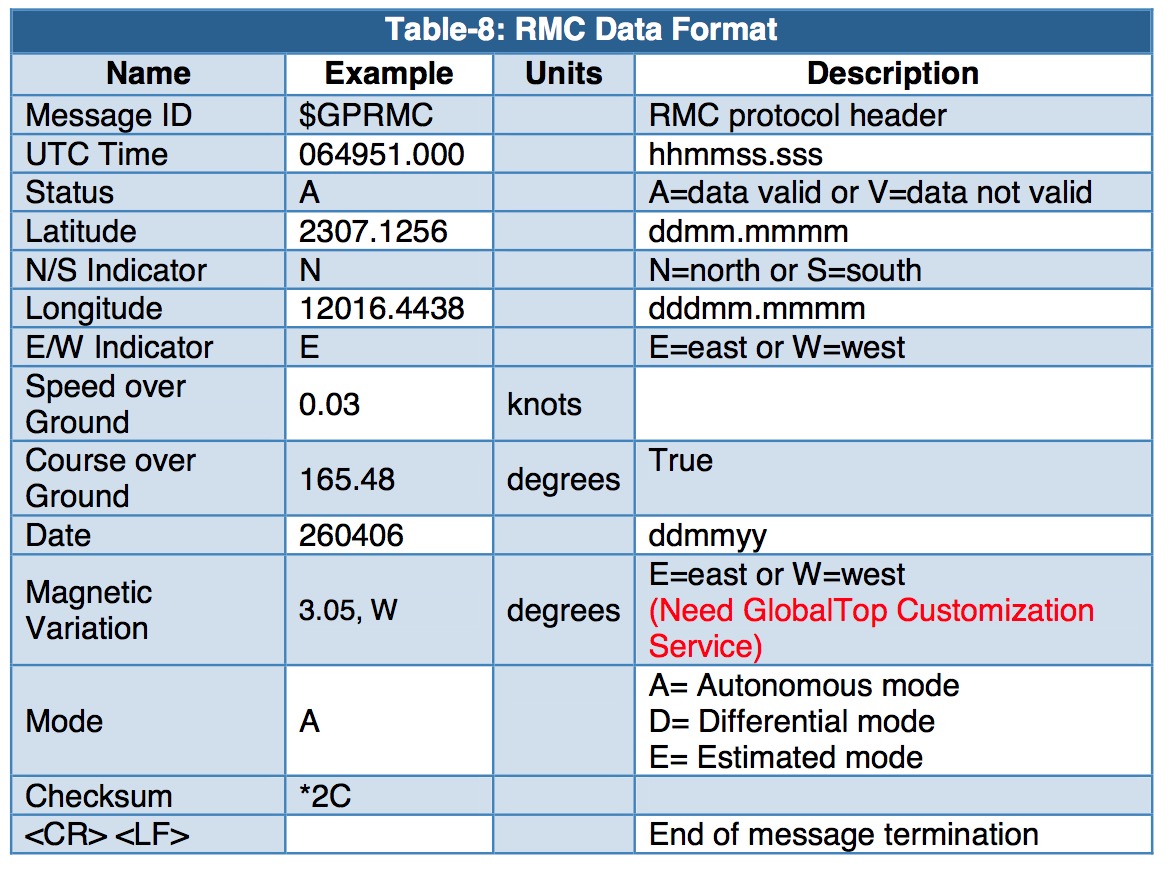
 Well, yes, it takes literally only minutes to assemble and test a GPS sensor plus real-time clock through the USB port on your computer, and that computer can be a Windows PC, Mac, any Linux system such as the Raspberry Pi, or even an Android system. All it takes is having the right components and connect them as shown in the image to the left.
Note: If you are interested connecting a GPS sensor with real-time clock to an Arduino Due (or a Mega 2560) have a look at my post Electronic Logging Device (ELD) - GPS And Real-Time Clock (RTC) Breakout Board For The Arduino Due.
The necessary components for this project are the GPS sensor with integrated real-time clock, a USB to UART breakout board (either USB Mini or USB Micro) and, of course, some wires plus the USB cable.
Needless to say, but you can get both, the GPS sensor and the USB breakout board, through our website (see references below).
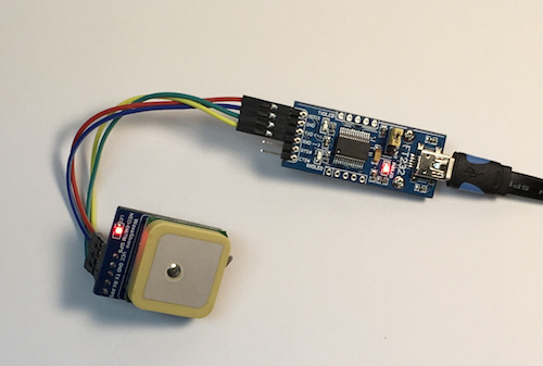
Our UART GPS Module With Real-Time Clock features the NEO-7M-C chip onboard, a high-gain active antenna, an IPX interface for connecting different active, external antennas, and a chargeable backup battery, which keeps the ephemeris data when power down and supports hot starts.
Specifications
- TTL level, compatible with 3.3V/5V systems
- Baud rate 9600 only
- Operating voltage: 2.7V-5.0V (VCC input)
- Operating current: 35mA
- TXD/RXD impedance: 510Ω
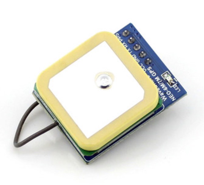
We offer two versions of the USB breakout board:
Both breakout boards are pin-compatible with each other, and they come with drivers for Mac, Linux, Android, WinCE, and Windows 7/8/8.1/10.
Note: If you are interested in a different serial connection, we also offer:
The difference between these serial breakout boards and the USB board is that the USB board is powered by the PC and the GPS sensor, in turn, is powered by the USB board. Using RS232 or RS485 breakout boards will require an additional 5 VDC power supply.
Wiring
| GPS Module | USB Breakout Board |
| VCC | VCC |
| GND | GND |
| RXD | TXD |
| TXD | RXD |
Note: The RTS and CTS signals on the USB breakout board can be left open. As I mentioned previously, the USB board will power the GPS module.
Display GPS And Real-Time Clock Data
Reading and displaying the GPS and Real-Time information is as easy as assembling the components. I used the RealTerm terminal software on my Windows 10 machine and connected it to the corresponding COM port and set a baud rate of 9600.
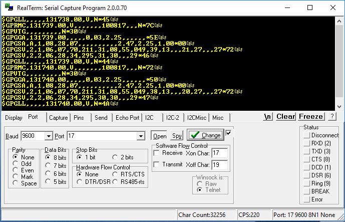
And, of course, you can use any other terminal software.
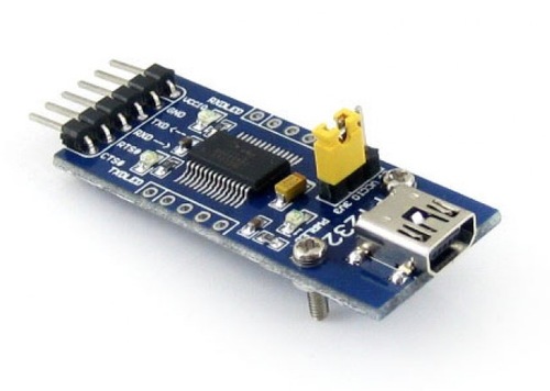
The data output, however, is where most of the work lies ahead, i.e. decoding the received the information. The GPS sensor provides data according to NMEA 0183 (as does any standard GPS sensor), and decoding the data is fairly easy to accomplish with the following information, the so-called NMEA output sentences, at hand.
Free software libraries for parsing or building NMEA sentences
- C library (parsing and building NMEA)
- Java library (decoding and encoding of NMEA)
- Java/Eclipse plug-in (parsing NMEA)
- C# library (parsing NMEA)
- Ruby gem (parsing NMEA and AIS)
- C#/Java library (parsing and building NMEA)
NMEA Output Sentences
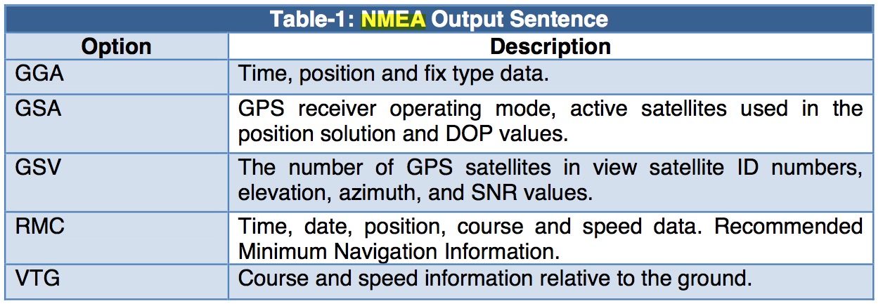
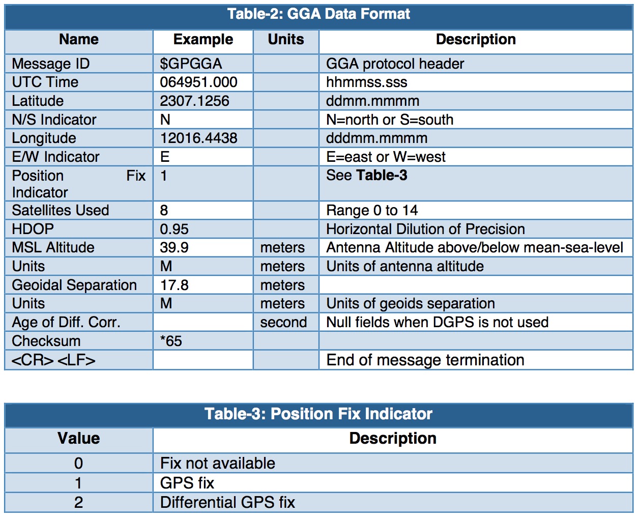
GGA—Global Positioning System Fixed Data. Time, Position and fix related data
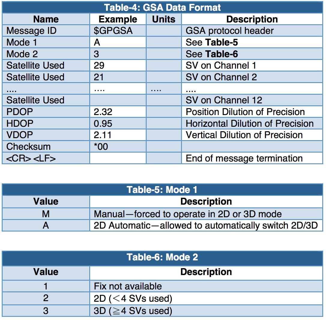
GSA—GNSS DOP and Active Satellites
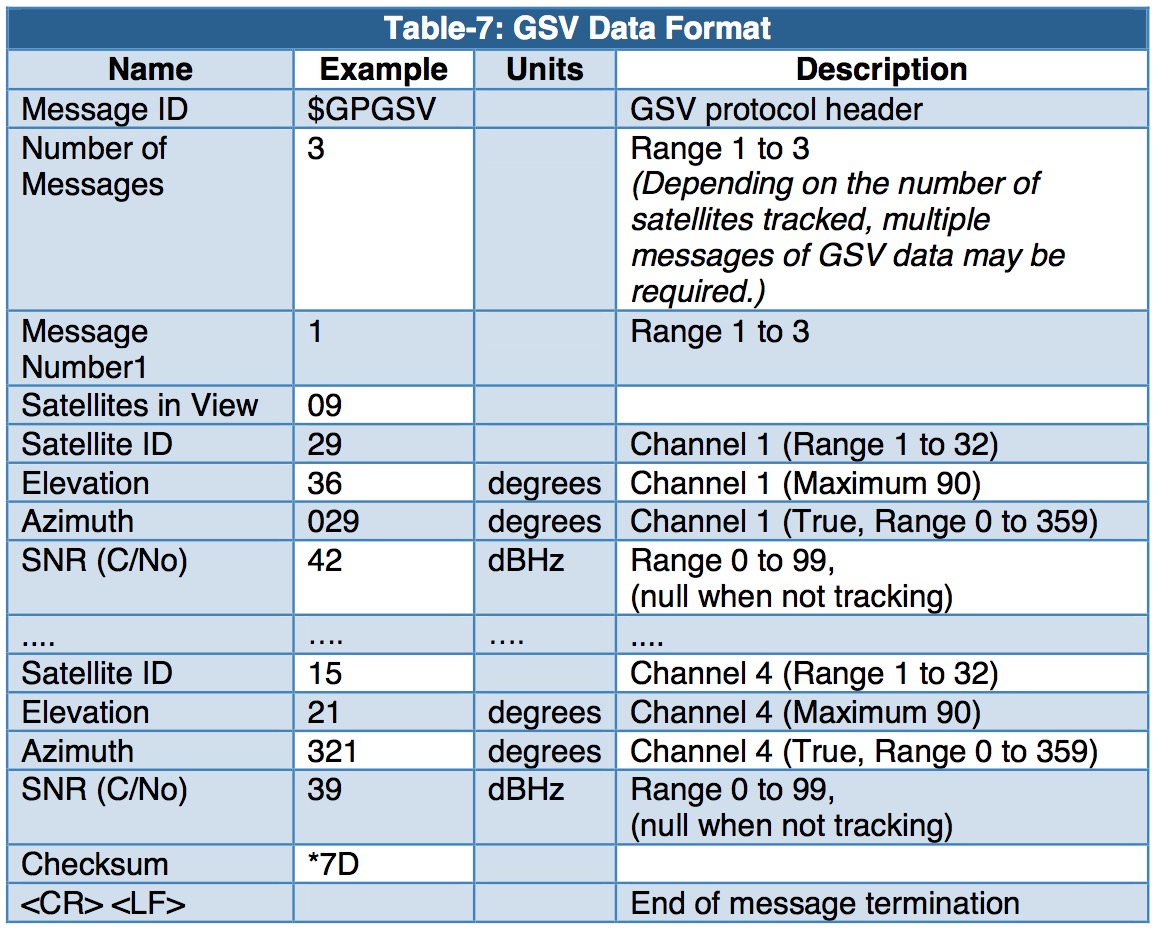
GSV—GNSS Satellites in View
RMC—Recommended Minimum Navigation Information