 Loading... Please wait...
Recent Posts
Controller Area Network (CAN Bus) Tutorial - Message Frame Format
Posted by on
The following is an excerpt from A Comprehensible Controller Area Network by Wilfried Voss.

This section will examine the exact structure of both data and remote message frames bit by bit.
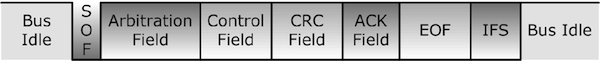
Per definition, a CAN data or remote frame has the following components:
- SOF (Start of Frame) - Marks the beginning of data and remote Frames
- Arbitration Field – Includes the message ID and RTR (Remote Transmission Request) bit, which distinguishes data and remote frames
- Control Field – Used to determine data size and message ID length
- Data Field – The actual data (Applies only to a data frame, not a remote frame)
- CRC Field - Checksum
- ACK Field – Acknowledgement of checksum check
- EOF (End of Frame) – Marks the end of data and remote frames
- IFS – Interframe Space
Both, Data Frame and Remote Frame, are very similar. Basically, the Remote Frame is a Data Frame without the Data Field.
Data Frame

Remote Frame
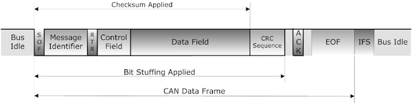
The following picture shows the bitstream of a data frame in detail.
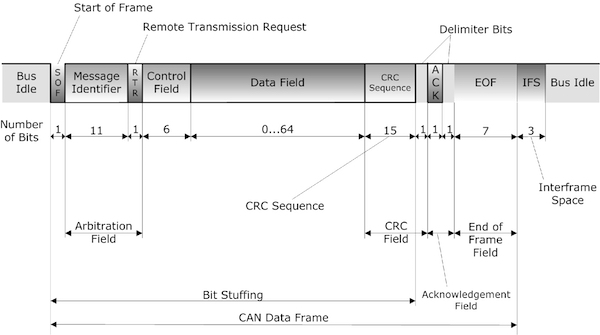
As shown in the previous picture, the entire frame has a length between 47 and 111 bits, depending on the length of the data field, which can be between 0 and 8 bytes (0 and 64 bits).
At a baud rate of 1 MBit/sec, this translates into a transmission time between 47 (remote frame) and 111 (data frame with 8 bytes of data) microseconds.[1]
The following components of a CAN data or remote frame are considered static fields since their data level is static (recessive):[2]
- CRC Delimiter
- ACK Delimiter
- End of Frame Field
- Intermission FieldThese components are also used to check the consistency of a data or remote frame (see also Chapter 8 - Error Detection and Fault Confinement).
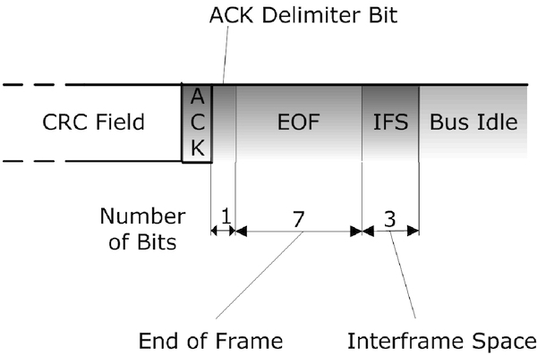
Each CAN message frame, regardless of the message ID length, will be terminated by a sequence of 11 recessive bits: The ACK Delimiter bit in the Acknowledgement Field (1 bit), the End of Frame Field (7 bits), and the Intermission Field (3 bits).
The individual frame elements are:
SOF (1 Bit)
The dominant Start of Frame (SOF) bit represents the start of a Data/Remote Frame and, in all consequence, also starts the arbitration sequence (the arbitration field follows right after the SOF bit). Thus, before attempting to access the bus, a CAN node must wait until the bus is idle. A sequence of 11 recessive bits detects an idle bus, i.e., the sequence of ACK Delimiter bit in the Acknowledgement Field (1 bit), the End of Frame Field (7 bits), and the Intermission Field (3 bits).
The falling (leading) edge of the SOF bit (transition from recessive to dominant level), sent by the first node that attempts to access the bus, also serves as a mechanism to synchronize all CAN bus nodes.
Arbitration Field (12 or 32 Bits)
The arbitration field contains of two components:
- 11/29 Bit Message Identifier, first Bit is MSB. As will be explained later, the CAN message ID can be 11 or 29 bits long.
- RTR (Remote Transmission Request) indicates either the transmission of a Data Frame (RTR = 0) or a Remote-Request Frame (RTR = 1).
A low message ID number represents a high message priority.
A Data Frame has higher priority than a Remote Frame.
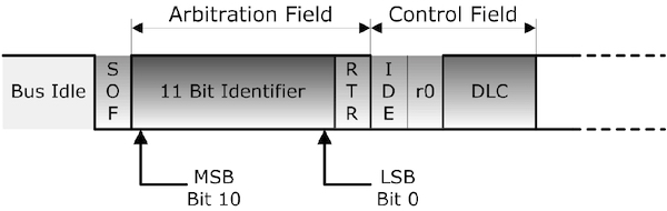
The total length of the arbitration field is 12 bits when an 11 bit message identifier is used (see picture below).
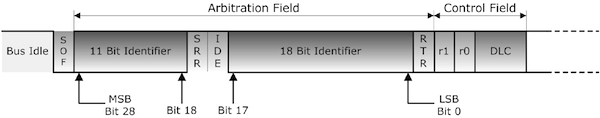
As shown in the picture, the total length of the arbitration field will be 32 bit with a 29 bit identifier (see also Chapter 4.6 – Extended CAN Protocol).
An 11 bit identifier (standard format) allows a total of 211 (= 2048) different messages. A 29 bit identifier (extended format) allows a total of 229 (= 536+ million) messages.
The IDE (Identifier Extension) bit belongs to:
– The Control Field of the standard format (11 bit message identifier)
– The Arbitration Field of the extended format (29 bit message identifier)
Control Field (6 Bits)
The 4 LSB bits of the Control Field specify the length of the data block (DLC = Data Length Code), the MSB bit (IDE = Identifier Extension) indicates either standard 11-Bit format (Bit = 0) or 29-Bit extended format (Bit = 1).
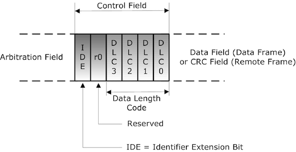
As will be explained in the following chapter, the CAN message ID can be 11 or 29 bits long. The IDE bit became active with the release of the CAN 2.0B standard (i.e., the extension of the message identifier from 11 to 29 bits). The previous standard CAN 2.0A referred to bits r0 and r1 (instead of IDE), which were, at the time, reserved for future purposes. Both bits, r0 and r1, were always sent as dominant (zero), which, according to standard CAN 2.0B, indicates an 11-bit identifier per default.
The Data Length Code (DLC) is usually set to a value between 0 and 8, indicating a data field length between 0 and 8 bytes. A value greater than 8 is permissible for application-specific purposes. In this case, the sending node must send 8 data bytes, while the receiving nodes expect 8 bytes.
Remote frames can only be transmitted with a DLC (Data Length Code) identical to the DLC of the corresponding data frame. Due to a limitation of contention-based arbitration, simultaneous transmission of remote frames with different DLCs will lead to irresolvable collisions.
Data Field (0 to 8 bytes)
Maximum 8 bytes, first Bit is MSB.
CRC Field (16 Bits)
The CRC (Cyclical Recovery Checking) Field contains the CRC Sequence and a CRC Delimiter Bit.
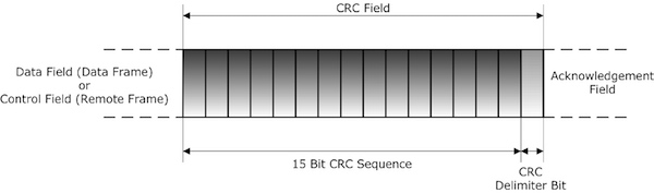
The 15 bit CRC Segment contains the frame check sequence spanning from SOF (Start of Frame), through the arbitration field, control field and data field. Stuffing Bits are not included (see also Chapter 7.2 – Bit Stuffing).
The CRC Delimiter Bit (always recessive, i.e., 1), following right behind the CRC Segment, allows for CRC processing time.
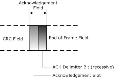
Acknowledgement Field (2 Bits)
The Acknowledgement Field contains a 1-bit Acknowledgement Slot plus the ACK Delimiter Bit (which is always recessive).
Unlike other serial communications, such as RS232, the acknowledgment field does not serve as a signal for the successful or unsuccessful reception of a message by a receiving node (consider that there may be numerous receiving nodes in a CAN network). The acknowledgment field serves as a confirmation of a successful CRC (checksum) check by the receiving nodes in the network.
During the ACK slot, the message transmitting node switches to receive mode by sending a recessive signal to the bus. At the same time, all other nodes in the network accomplish their individual CRC (checksum) check (according to the CAN standard, all nodes must determine the checksum in the same standardized way) and output a dominant signal to the bus when the check was successful.
The message transmitting node monitors the bus and expects a dominant level during the ACK slot. This will be the case when either one of the receiving CAN Bus nodes outputs a dominant level.
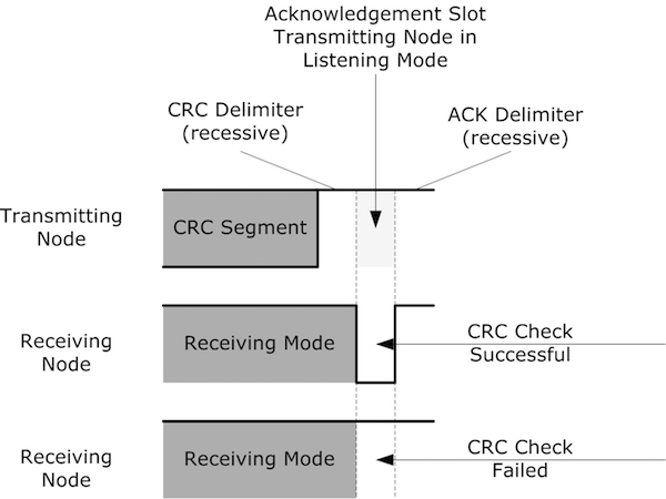
If all nodes in the network determine a checksum error, meaning the sending node monitors a recessive level in the ACK slot, it is clear that the sending node calculated a wrong checksum. The error is therefore local at the sending node.
Any receiving node detecting a checksum error will post an error frame to the bus, i.e., right after the completed acknowledgment field. With this scenario, it is possible to determine whether or not the actual malfunction is with that particular receiving node.
The ACK slot may remain dominant, while at the same time, an error is reported by only one receiving node, meaning this single node will send out an error frame. The error is therefore local at that particular receiving node.
The CAN standard allows the so-called “self-retirement” (or self-removal) of nodes from the network due to an excessive number of transmit or receive errors (see also Chapter 8 – Error Detection and Fault Confinement).
The ACK Delimiter Bit is always recessive. This is necessary to distinguish a successful acknowledgment from an occurring error frame. An error frame starts with at least six successive dominant bits, meaning the first bit of an error frame will override the ACK Delimiter Bit (see also Chapter 4.7 – Error Frame).
End-of-Frame Field (7 bits, recessive)
Each data or remote frame is terminated by a bit sequence of 7 recessive bits.
Each CAN message frame, regardless of the message ID length, will be terminated by a sequence of 11 recessive bits: The ACK Delimiter bit in the Acknowledgement Field (1 bit), the End of Frame Field (7 bits), and the Intermission Field (3 bits).
This last statement is true unless an Overload Frame occurs (see also Chapter 4.8 – Overload Frame).
More specifically: With the combination of the EOF Field and the preceding recessive ACK Delimiter Bit, each message (data and remote) frame is terminated by eight recessive bits plus, unless an overload frame occurs, the three recessive bits of the Intermission Field.
As shown in the following picture, the up to 11 recessive bits at the end of a message frame are not subject to bit stuffing error detection since the bit stuffing applies only between the SOF (Start Of Frame) bit and (including) the CRC Sequence (see also Chapter 7.2 – Bit Stuffing).
Interframe Space (3 bits, recessive)
The Interframe Space represents the minimum space between frames of any type (data, remote, error, overload) and the following data or remote frame. During the Interframe Space (intermission), no node can start transmitting a data or remote frame. Only the signaling of an overload condition is allowed (see Chapter 4.8 – Overload Frame). There is no Interframe space between error and overload frames. The Interframe Space can not necessarily be considered to be a part of a data or remote frame; however, in a well-functioning CAN network, it will always follow behind a data or remote frame. For more detailed information, see also Chapter 4.9 – Interframe Space.

[1] The information on frame length and the derived transmission times do not include any stuffing bits (See also Chapter 7.2 – Bit Stuffing). In all consequence, the number of average bit stuffing needs to be applied. For more detailed information on frame length and transmission time, refer to Chapter 4.10 – Frame Length and Transmission Times.
[2] The ISO 11898-1 and the Bosch/CiA standard refer to the static fields in various chapters but omit a precise definition.

PiCAN 2 - CAN Bus Interface for Raspberry Pi
This PiCAN2 board provides Controller Area Network (CAN) Bus capabilities for the Raspberry Pi. It uses the Microchip MCP2515 CAN controller with MCP2551 CAN transceiver. Connection are made via DB9 or 3-way screw terminal.
There is an easy-to-install SocketCAN driver, and programming can be accomplished in C or Python.
The PiCAN board is fully compatible with the new Raspberry Pi 4 Model B.