 Loading... Please wait...
Recent Posts
Controller Area Network (CAN Bus) Tutorial - CAN Bus Controller Firmware
Posted by on
The following is an excerpt from A Comprehensible Controller Area Network by Wilfried Voss.

As demonstrated in the image below, the ISO/OSI Reference Model specifies seven levels beginning with the physical connection to the actual user application, i.e., the Application Layer.
The standard CAN implementation bypasses the connection between the Data Link Layer and the Application Layer to save on valuable memory resources by minimizing the overhead and, as a result, gaining performance for embedded solutions with limited resources.
Layers 3 through 6, i.e., all layers above the Data Link Layer, require additional software resources. They are provided by higher layer protocols such as CANopen, DeviceNet, and J1939 (see Chapter 3.5 - Higher Layer Protocols).
For more information on the OSI Reference Model refer to:
CertificationZone.com OSI Reference Model Pocket Guideby Howard C. Berkowitz - ISBN: 1890911143
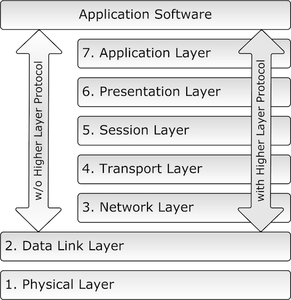
The Application Layer is the layer that interacts with the operating system or application of the CAN device.
The Data Link Layer connects the actual data to the protocol to send, receive, and validate data. Under CAN, it represents the data exchange, including error detection/recovery and fault confinement, transmission acknowledgments, etc., and all the ingenious features as previously described in Chapter 2 - Main Characteristics.
The Physical Layer represents the actual hardware, i.e., the physical connection between nodes in a network and the electrical signal characteristics such as voltage levels and timing.
Whenever you attempt to add software functions between the CAN Data Link Layer and the Application Layer, you will add functionalities already covered by off-the-shelf available higher layer protocols such as CANopen and DeviceNet.
The software development engineer will benefit from the fact that under CAN, the two lowest layers, the Physical Layer and Data Link Layer, are already integrated into silicon. This reduces the software development process by concentrating solely on the coding of the actual application software.
Most CAN chip manufacturers and vendors in the CAN business provide source code (e.g., for LINUX) and libraries (e.g., Windows APIs) for all function calls representing the connection between the Data Link Layer and the Application Layer.
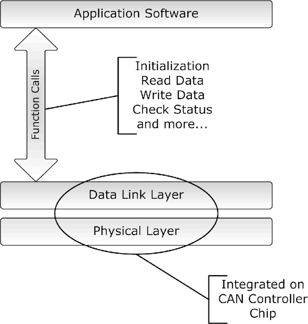
The nature of the necessary function calls is identical to those needed for the access of any hardware device (drivers):
- Initialization
- Read Data
- Write Date
- Check Status
Naturally, this is just an elementary list of function calls. Most code libraries provide extended functionality like the determination of the busload and more.

PiCAN 2 - CAN Bus Interface for Raspberry Pi
This PiCAN2 board provides Controller Area Network (CAN) Bus capabilities for the Raspberry Pi. It uses the Microchip MCP2515 CAN controller with MCP2551 CAN transceiver. Connection is made via DB9 or 3-way screw terminal.
There is an easy-to-install SocketCAN driver, and programming can be accomplished in C or Python.
The PiCAN board is fully compatible with the new Raspberry Pi 4 Model B.