 Loading... Please wait...
Recent Posts
CAN Bus Data Traffic Simulation With Arduino Due
Posted by on
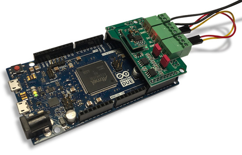 When working on a CAN bus or SAE J1939 project, it can be extremely helpful when the expected CAN Bus data traffic can be simulated rather than connecting your system to a running vehicle or automation control. The following project does exactly that with little effort for designing CAN data frames and their frequency. As a hardware I have been using our Arduino-Based ECU Development Board With Dual Bus Interface as shown in the image to the left.
As an alternative, you can also use your existing Arduino Due in combination with our Dual Can Bus Interface For Arduino Due.
The board is not an Arduino shield in the common sense. It incorporates dual CAN transceivers required by the two integrated CAN ports on the Arduino Due while allowing the operation with any Arduino-compatible shield that supports the necessary 3.3 VDC power requirements.
By combining our dual CAN port interface, the Arduino DUE microcontroller, an OBD2 or SAE J1939 cable, and open-source software libraries you are ready to go with powerful a turn-key Arduino-based dual CAN bus solution. Leverage the 32-bit processing capability of the Arduino DUE plus the built-in CAN ports for your next prototype.
Features
- 2 CAN ports with three-pin terminal connectors
- 3 LEDS (Power, CAN Activity Port 1, CAN Activity Port 2)
- Termination resistors switchable per jumper
But coming back to our project, I have modified and extended one of our existing sketches to allow the definition of CAN Bus data frames and their frequency. Here is an example:
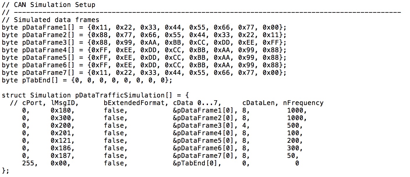
The first part shows the definition of a number of (randomly designed) CAN data frames. In the following pDataTrafficSimulation structure, you define the port number (0/1; the Arduino Due supports two CAN ports), the message ID, choice of format (standard 11-bit or extended 29-bit message ID length), pointer to the data frame, data length, and finally the frequency in milliseconds.
Note: For more information on the timer control, see my post Interrupt-Controlled Timer Function for the Arduino Due.
I don't want to go too deep into the details of the program, but please be aware that the software has its limitation in terms of busload. I have been using the CAN driver software as developed by Collin Kidder and published at https://github.com/collin80/due_can. However, with my tendency to push applications to their limit, I am still finding inconsistencies in the code that limit the performance to a certain degree.
Please pay special attention to the line int nTxMailboxes = 6; in the main code module. Out of the 7 available CAN controller mailboxes, I used 6 for transmission to assure proper function. In the current setup CAN messages will get lost when these 6 mailboxes are exhausted. The code attempts to buffer the data in such a case but in reality it doesn't work (even though I cannot entirely rule out that I am missing something). Nevertheless, I will work on an update to rectify this little flaw. For a basic simulation, this sketch will do just fine.
Click here to download the Data Traffic Simulation sketch (zip file)...
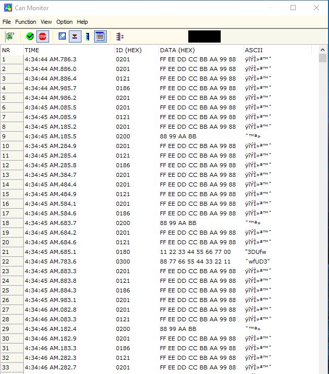
Last, but not least, here is the proof of concept:
Please feel free to contact me through the Contact Us page on this website in case you have questions or comments.