Recent Posts
CAN Bus And SAE J1939 Bus Voltage
Posted by on
CAN Bus Medium
According to ISO-11898 specification, the CAN bus medium must support two logical states: Recessive and dominant.
A CAN controller with its TTL output uses an additional line driver (transceiver) to provide the standard CAN Bus level. The dominant level (TTL = 0V) always overrides a recessive level (TTL = 5V), which is, especially during bus arbitration. As demonstrated in picture below, the CAN bus level will be dominant in case any number of nodes in the network output at a dominant level. The CAN bus level will only be recessive when all nodes in the network output a recessive level.
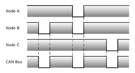
CAN Node Output and Bus Level
An equivalent from some electronics basics will explain the relationship between node output and the resulting bus level as shown in the picture below.
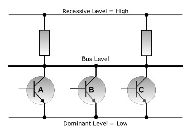
Open Collector Principle on a CAN bus
This example uses three nodes in a CAN network, in this case represented by three transistors in open-collector (“Wired And”) configuration. The bus level will be at low level (dominant) in case any number of transistors in the network output a dominant level. The bus level will only be at a high level (recessive) when all transistors in the network output a recessive level.
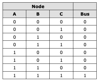
Wired And
Bus Signal Level
As shown in the below picture, the CAN bus level typically ranges (Common-Mode-Voltage = 0V) between 1.5 (CAN_L during dominant bit) and 3.5 Volts (CAN_H during dominant bit). However, the actual signal status, recessive or dominant, is based on the differential voltage Vdiff between CAN_H and CAN_L.
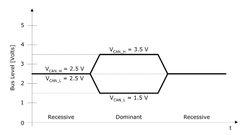
CAN Bus Level

Differential Voltage
During bus arbitration, several CAN Bus nodes may transmit a dominant bit simultaneously to the bus. In this case, Vdiff will exceed the nominal level as seen during single operation, i.e. when the bus is driven by only one node.
The advantage of using a differential voltage between CAN_H and CAN_L lies in its resistance to electromagnetic interferences (EMI). Any EMI will affect both wires in the same way, but the differential voltage level will remain constant.
Bus Connection
In order to connect to the physical CAN Bus, a CAN controller with its TTL output uses an additional line driver (transceiver) to provide the standard CAN Bus level.
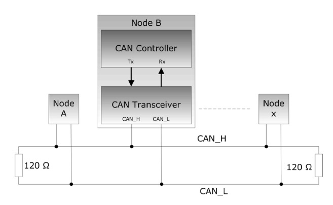
CAN Controller and Transceiver
The transceiver converts the standard TTL level (in some cases 3 V instead of the standard 5 V) into a differential voltage, i.e. the CAN bus level (See picture 9.4.1) and vice versa.
The next picture demonstrates both signals, TTL and CAN bus.
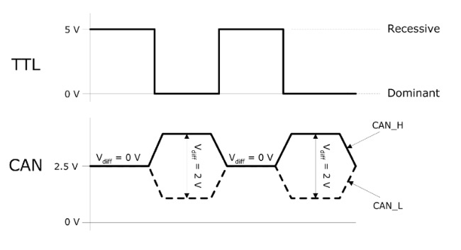
Physical Bit Representation
The actual signal status, recessive or dominant, is based on the differential voltage Vdiff between CAN_H and CAN_L.

Differential Voltage
Vdiff will be 2V during a dominant bit and 0V during a recessive bit.
 Loading... Please wait...
