- Home
- Documentation
- A Brief Introduction to the SAE J1939 Protocol
A Brief Introduction to the SAE J1939 Protocol
The Society of Automotive Engineers (SAE) Truck and Bus Control and Communications Subcommittee has developed a family of standards concerning the design and use of devices that transmit electronic signals and control information among vehicle components. SAE J1939 and its companion documents have quickly become the accepted industry standard and the vehicle network of choice for off-highway machines in applications such as construction, material handling, mass transportation, forestry machines, agricultural machinery, maritime and military applications.
Note: It is fair to say that the SAE J1939 vehicle protocol is primarily used on diesel engines, which covers all previously mentioned applications.
J1939 is a higher-layer protocol based on Controller Area Network (CAN). It provides serial data communications between microprocessor systems (also called Electronic Control Units - ECU) in any kind of heavy-duty vehicles. The messages exchanged between these units can be data such as vehicle road speed, torque control message from the transmission to the engine, oil temperature, and many more.
Note: Even though being around for many years, the SAE J1939 protocol is still gaining popularity, especially in view of the increased use of fleet management systems, which, unavoidably, will need data from the vehicle network, for instance, to calculate maintenance cycles. Fleet management is also tightly associated with the Internet of Things (IoT), and transportation is considered one of the fastest growing markets for IoT.
Introduction to Controller Area Network
Controller Area Network (CAN) is a serial network technology that was originally designed for the automotive industry, especially for European cars, but has also become a popular bus in industrial automation as well as other applications. The CAN bus is primarily used in embedded systems, and as its name implies, is a network technology that provides fast communication among microcontrollers up to real-time requirements, eliminating the need for the much more expensive and complex technology of a Dual-Ported RAM.
CAN is a two-wire, half duplex, high-speed network system, that is far superior to conventional serial technologies such as RS232 in regards to functionality and reliability and yet CAN implementations are more cost effective.
While, for instance, TCP/IP is designed for the transport of large data amounts, CAN is designed for real-time requirements and with its 1 MBit/sec baud rate can easily beat a 100 MBit/sec TCP/IP connection when it comes to short reaction times, timely error detection, quick error recovery and error repair.
CAN networks can be used as an embedded communication system for microcontrollers as well as an open communication system for intelligent devices. Some users, for example in the field of medical engineering, opted for CAN because they have to meet particularly stringent safety requirements.
Similar requirements had to be considered by manufacturers of other equipment with very high safety or reliability requirements (e.g. robots, lifts and transportation systems).
The greatest advantage of Controller Area Network lies in the reduced amount of wiring combined with an ingenious prevention of message collision (meaning no data will be lost during message transmission).
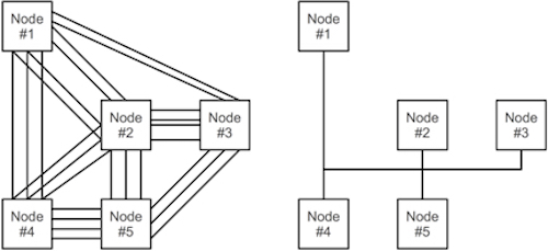
Without CAN Vs. With CAN
The following shows a need-to-know overview of CAN’s technical characteristics.
Controller Area Network
- Is a serial networking technology for embedded solutions.
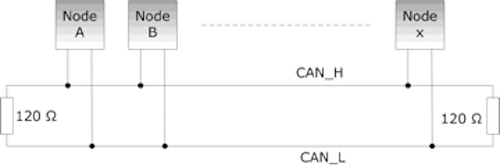
- Needs only two wires named CAN_H and CAN_L.
- Operates at data rates of up to 1 Megabit per second.
- Supports a maximum of 8 bytes per message frame.
- Does not support node IDs, only message IDs. One application can support multiple message IDs.
- Supports message priority, i.e. the lower the message ID the higher its priority.
- Supports two message ID lengths, 11-bit (standard) and 29-bit (extended).
- Does not experience message collisions (as they can occur under other serial technologies).
- Is not demanding in terms of cable requirements. Twisted-pair wiring is sufficient.
The SAE J1939 Higher Layer Protocol
Even though extremely effective in automobiles and small, embedded applications, CAN alone is not suitable for projects that require a minimum of network management and messages with more than eight data bytes.
As a consequence, higher layer protocols (additional software on top of the CAN physical layer) such as SAE J1939 for vehicles were designed to provide an improved networking technology that support messages of unlimited length and allow network management, which includes the use of node IDs (CAN supports only message IDs where one node can manage multiple message IDs).
SAE J1939
- Is a standard developed by the Society of Automotive Engineers (SAE)
- Defines communication for vehicle networks (trucks, buses, agricultural equipment, etc.)
- Is a Higher-Layer Protocol using CAN as the physical layer
- Uses shielded twisted pair wire
- Applies a maximum network length of 40 meters (~120 ft.)
- Applies a standard baud rate of 250 Kbit/sec
- Allows a maximum of 30 nodes (ECUs) in a network
- Allows a maximum of 253 controller applications (CA) where one ECU can manage several CAs
- Supports peer-to-peer and broadcast communication
- Supports message lengths up to 1785 bytes
- Defines a set of Parameter Group Numbers (PGNs, predefined vehicle parameters)
- Supports network management (includes node IDs and an address claiming procedure)
Compared to other, function-driven protocols such as CANopen and DeviceNet, SAE J1939 is primarily data-driven. In fact, J1939 provides a far better data bandwidth than any of these automation protocols.
J1939 data packets contain the actual data and a header, which contains an index called Parameter Group Number (PGN). A PGN identifies a message's function and associated data. J1939 attempts to define standard PGNs to encompass a wide range of automotive, agricultural, marine and off-road vehicle purposes.

The actual data in the data field is described by the SPNs.
Note: You will need a copy of the SAE J1939/71 standard for a detailed description of all PGNs and SPNs. You may find some of them by browsing the Internet, but be aware that there is no complete online reference. A description of all PGNs is out of the scope of this book.
SAE J1939 Starter Kit And Network Simulator
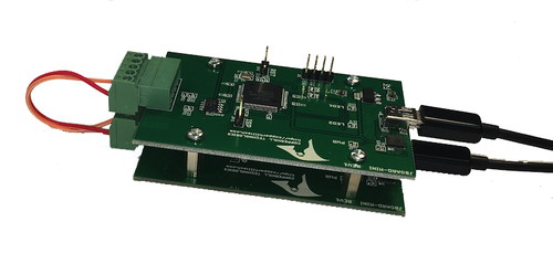
The JCOM.J1939 Starter Kit And Network Simulator is designed to allow the experienced engineer as well as the beginner to experiment with SAE J1939 data communication without the need of connecting to a real-world J1939 network, i.e., a diesel engine.
In order to establish a network, you need at least two nodes. That fact applies especially to CAN/J1939, where the CAN controller will shut down after transmitting data without receiving a response. For that reason, our jCOM.J1939 Starter Kit And Network Simulator consists of two J1939 nodes, namely our jCOM.J1939.USB, an SAE J1939 ECU Simulator Board With USB Port.
The jCOM.J1939.USB gateway board is a high-performance, low-latency vehicle network adapter for SAE J1939 applications. The board supports the full SAE J1939 protocol according to J1939/81 Network Management (Address Claiming) and J1939/21 Transport Protocol (TP).
Parameter Group Numbers (PGN)
SAE J1939 is a very ingeniously designed protocol that takes a resourceful advantage of the CAN 29-Bit message identifier. Rather than relying on a myriad of protocol functions, SAE J1939 uses predefined parameter tables, which keeps the actual protocol on a comprehensible level.
Parameters groups are, for instance, engine temperature, which includes coolant temperature, fuel temperature, oil temperature, etc. Parameter Groups and their numbers (PGN) are listed in SAE J1939 (roughly 300 pages) and defined in SAE J1939/71, a document containing roughly 800 pages filled with parameter group definitions plus suspect parameter numbers (SPN). In addition, it is possible to use manufacturer-specific parameter groups.
From a programming aspect, it is important to know that the combination of PGN, message priority, and the application’s node (source) address represents the 29-Bit message identifier of the CAN message as demonstrated in the following image.
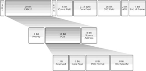
Note: For more detailed information on the J1939 message format, please refer to the official SAE documentation or my book “A Comprehensible Guide to J1939.” However, the definition of, for instance, “PDU Format” and “PDU Specific,” come with a great potential of confusing the J1939 novice, i.e. the educational value is questionable.
Parameter Groups
Parameter Groups contain information on parameter assignments within the 8-byte CAN data field of each message as well as repetition rate and priority.
The following is an example of a parameter group definition as listed in SAE J1939/71:
- PGN 65262 - Engine Temperature
- Transmission Rate: 1 sec
- Data Length: 8 bytes
- Default Priority: 6
- PG Number: 65262 (FEEEhex)
- Description of Data
- Byte 1: Engine Coolant Temperature – SPN 110
- Byte 2: Fuel Temperature – SPN 174
- Byte 3, 4: Engine Oil Temperature – SPN 175
- Byte 5, 6: Turbocharger Oil Temperature- SPN 176
- Byte 7: Engine Intercooler Temperature - SPN 52
- Byte 8: Engine Intercooler Thermostat Opening - SPN 1134
Suspect Parameter Numbers (SPN)
A Suspect Parameter Number (SPN) is a number assigned by the SAE to a specific parameter within a parameter group. It describes the parameter in detail by providing the following information:
- Data Length in bytes
- Data Type
- Resolution
- Offset
- Range
- Reference Tag (Label)
SPNs that share common characteristics are grouped into Parameter Groups (PG) and they will be transmitted throughout the network using the Parameter Group Number (PGN).
To follow up on the previous example (PGN 65262), the parameter Engine Coolant Temperature is described by SPN 110 in the following way:
- SPN 110 - Engine Coolant Temperature
Temperature of liquid engine cooling system - Data Length: 1 Byte
- Resolution: 1 deg C / Bit
- Offset: -40 deg C
- Data Range: -40 to 210 deg C
- Type: Measured
- Reference: PGN 65262
PGN Range
Program Parameter Numbers (PGNs) are in a range of:
0x0000 – 0xEEFF: 239 Peer-to-Peer messages defined by SAE
0xEF00 – 0xEFFF: 1 Peer-to-Peer message for proprietary use
0xF000 – 0xFEFF: 3840 Broadcast messages defined by SAE
0xFF00 – 0xFFFF: 256 Broadcast messages for proprietary use
Note: The SAE J1939 allows two types of messages, peer-to-peer (= direct node communication) and broadcast. Broadcast messages (their message ID includes the address of the sending node) are distributed to all nodes and the nodes decide whether to use it or not. Peer-to-Peer messages use a message ID that includes the transmitter and receiver address. Node addresses are always 8 bits long.
More Resources
- SAE J1939 - Serial Control And Communications Vehicle Network - PPT Presentation...
- SAE J1939 Address Claim Procedure - SAE J1939/81 Network Management
- ARD1939 - SAE J1939 Protocol Stack for Aduino
- jCOM1939 Monitor - SAE J1939 Monitor, Analyzer, And ECU Simulator
- SAE J1939 ECU Simulation With Raspberry Pi
- SAE J1939 Project With Arduino Uno/Mega2560: Requesting & Simulating Vehicle Identification Number (VIN)
- Simulating SAE J1939 PGNs Used By Truck & Bus FMS (Fleet Management System) Standard
- SAE J1939 Bandwidth, Busload, And Message Frequency
- A Beginner's Guide to SAE J1939 Embedded Software Development
- Mapping of J1939 to CAN FD...
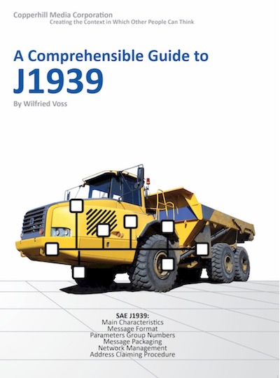
A Comprehensible Guide to J1939
SAE J1939 has become the accepted industry standard and the vehicle network technology of choice for off-highway machines in applications such as construction, material handling, and forestry machines. J1939 is a higher-layer protocol based on Controller Area Network (CAN). It provides serial data communications between microprocessor systems (also called Electronic Control Units - ECU) in any kind of heavy duty vehicles. The messages exchanged between these units can be data such as vehicle road speed, torque control message from the transmission to the engine, oil temperature, and many more.
The information in this book is based on two documents of the SAE J1939 Standards Collection: J1939/21 - Data Link Layer J1939/81 - Network Management A Comprehensible Guide to J1939 is the first work on J1939 besides the SAE J1939 standards collection. It provides profound information on the J1939 message format and network management combined with a high level of readability.
 Loading... Please wait...

