Product Description
Free Shipping Within the United States!
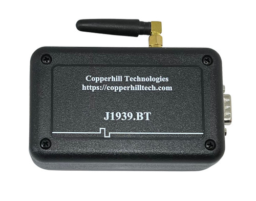
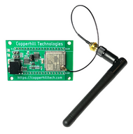
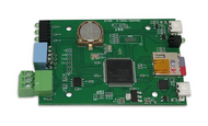
The J1939.BT gateway is a high-performance, low-latency, wireless vehicle network adapter for SAE J1939 applications. It allows any host device with a Bluetooth COM port to monitor SAE J1939 data traffic and communicate with the SAE J1939 vehicle network. An SAE J1939 cable, suited for a 9-pin Deutsch connection, can be purchased as indicated above.
The gateway supports the full SAE J1939 protocol according to J1939/81 Network Management (Address Claiming) and J1939/21 Transport Protocol (TP). It is also supported by an extensive programming interface for Windows and Linux/Ubuntu applications, including full C/C++/C# source code for short time-to-market developments.
The strength of the gateway lies in the fact that the entire SAE J1939 protocol, including all timing requirements, is stored on-chip, thus taking the burden off the main system. The board uses a wireless Bluetooth COM port to communicate with the main system, i.e. all data transfer is handled through a standard COM port access. The communication protocol between the board and the main system is well documented and thus allows a porting to any computer system with a Bluetooth connection. Working source code libraries exist for Windows (C# under Visual Studio 2102/2013), Linux and its derivatives (C++ using Code::Blocks), and Raspberry Pi (C using the standard gcc compiler).
With all its features, the J1939.BT gateway allows the simulation of an SAE J1939 ECU (Electronic Control Unit) using embedded solutions such as the Raspberry Pi, BeagleBone, Arduino, Teensy, and others but also PCs running Windows, Linux (incl. Ubuntu, Fedora, etc.), Android, or iOS.
External BT Antenna
We chose an external antenna over an PCB type to assure best transmission quality. Research indicates that when a Bluetooth antenna is placed inside or next to a plastic enclosure, its RF signal is impeded by as much as 37.5%. As a result, the broadcast signal can shift from the official Bluetooth frequency range, between 2.4 and 2.4835GHz, to 2.159GHz.
Ref: Plastic enclosures may impede Bluetooth signals - EE Times...
Windows Software
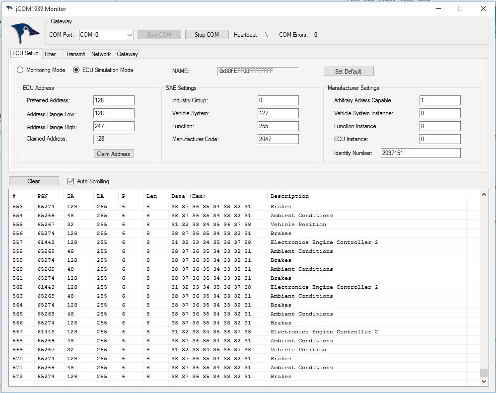 The communication protocol between the gateway and the host system (PC, Embedded System, Android System, etc.) is well documented, and we provide C source code to read and write CAN data frames.
In addition, the gateway is supported by our jCOM1939 Monitor, an SAE J1939 Monitoring, Analyzer and ECU Simulation software under Windows.
The jCOM1939 Monitor Software is the perfect tool to monitor, analyze, and simulate SAE J1939 data traffic.
The system combines a powerful monitoring software with our jCOM.J1939.BT that functions as an SAE J1939 to Bluetooth gateway.
A comprehensive and easy-to-use, easy-to-understand Windows software displays not only SAE J1939 data traffic; it also allows to scan the network, simulate an ECU (incl. full node address negotiation features), and respond to data request messages.
Features
- CAN Bus Interface - Fully ISO-11898 Compliant
- Onboard Interface For On-Site Firmware Update
- Bluetooth port with external antenna
- SAE J1939 Protocol Stack
- Extended Temperature Range of -40C to +85C
- Input Power Range of 7 VDC to 36 VDC
- Flame Retardant ABS Enclosure 3.29 x 2.42 x 1.00 in / 83.57 x 61.47 x 25.40 mm
- Environmentally friendly, RoHS compliant
Specifications
- CAN Interface
- CAN Controller integrated in microcontroller
- Fully ISO 11898-compliant
- Supports CAN 2.0A And CAN 2.0B
- Bit rate 250/500 kBaud
- Bluetooth Connection
- Fully certified Bluetooth version 2.1
- Backwards-compatible with Bluetooth version 2.0, 1.2, and 1.1
- Low power: 26 µA sleep, 3 mA connected, 30 mA transmit
- Bluetooth SIG certified
- Certifications: FCC, IC, CE
- SAE J1939 Protocol Stack
- Fully compliant to SAE J1939/21, SAE J1939/81
- Sending and receiving of messages (PGNs)
- Message filtering
- Request message processing
- BAM and CM transport protocol (TP) processing
- Static and arbitrary address claim
CAN Port
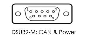
The CAN port has an on-board 120Ω (0.5W) termination resistor. This termination resistor can be connected or disconnected via an on-board slide switch.
CAN Bus Termination Resistor
The CAN Standard calls for a termination resistor at each end of the network (assuming there are two ends, which is sometimes difficult to determine due to the physical network structure). If you connect to an existing network, you will probably not need termination. However, during bench tests (e.g., when connecting to another single test instrument), you must ensure that both devices, including the BT gateway, are terminated.
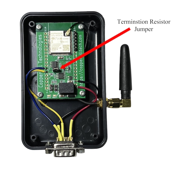
The J1939.BT gateway comes per default with a 120 Ohm termination resistor activated. To deactivate the resistor, open the enclosure and locate the pin jumper as indicated in below image, then remove the jumper.
Connecting Bluetooth to a Windows PC
Connecting Bluetooth to an Android Device
Note:
Some of the information below refers to our previous gateway version. However, the functionality as described is the same. We are working on updating the information.
Need Help with JCOM1939? We've Got You Covered!
 Got questions or running into issues with your JCOM1939 device or the JCOM1939 Monitor software? No worries — we’ve got you covered. We’ve put together a dedicated website packed with everything you need: user manuals, quick-start guides, troubleshooting tips, blog posts, videos, and more. It’s all organized to make your experience as smooth as possible.
And meet Carrie, our AI-powered assistant. She might be artificial, but she’s surprisingly good at helping you find exactly what you’re looking for.
Check it out at https://jcom1939.com — your one-stop shop for all things JCOM1939.
Documentation
- JCOM1939 Monitor Pro - User Manual (PDF)...
- JCOM1939 Monitor Pro - Download...
- JCOM.J1939 Serial Protocol & Programming Interface (PDF)...
Development Resources
- SAE J1939 ECU Simulation And Data Monitoring Under Linux...
- SAE J1939 ECU Simulator And Data Monitor for Raspberry Pi...
- JCOM1939 Monitor – Visual Studio C# Sample Code...
More Resources
- jCOM1939 Monitor, an SAE J1939 Monitoring, Analyzer and ECU Simulation software...
- Communication protocol between the gateway and the host system...
- Embedded ARM System Serves As SAE J1939 to Bluetooth Gateway...
- How CAN Bus Automatic Baudrate Detection Works And What To Consider When Connecting To A Network...
- ELD Concept: SAE J1939 Data Recording And Display Using Android Or iOS Devices...
- SAE J1939 to Bluetooth Gateway - Android Code (Java) Sample Code...
 Getting Started with Bluetooth Low Energy
With Bluetooth Low Energy (BLE), smart devices are about to become even smarter. This useful guide shows how this impressive wireless technology helps developers create mobile applications that share data with external hardware and how hardware engineers can obtain easy and reliable access to mobile operating systems.
This book renders a reliable, high-level overview of how devices use BLE to communicate with each other. You learn about valuable low-cost tools for developing and testing BLE-enabled mobile apps and embedded firmware and get examples using various development platforms, including iOS and Android for app developers and embedded platforms for product designers and hardware engineers.
- Understand how data is organized and transferred by BLE devices
- Explore BLE’s concepts, key limitations, and network topology
- Dig into the protocol stack to grasp how and why BLE operates
- Learn how BLE devices discover each other and establish secure connections
- Set up the tools and infrastructure for BLE application development
- Get examples for connecting BLE to iPhones, iPads, Android devices, and sensors
- Develop code for a simple device that transmits heart rate data to a mobile device
 Loading... Please wait...

