 Loading... Please wait...
Recent Posts
The Difference Between SAE J1939 And CAN Bus - The Extended CAN Bus Protocol
Posted by on
The following is an excerpt from A Comprehensible Controller Area Network by Wilfried Voss.

The standard CAN message frame uses an 11-bit message identifier (CAN 2.0A), which is sufficient for the use in regular automobiles and any industrial application, however, not necessarily for off-road vehicles.
The Society of Automotive Engineers (SAE) Truck and Bus Control and Communications Subcommittee had developed a family of standards concerning the design and use of devices that transmit electronic signals and control information among vehicle components. As a result, the higher layer protocol SAE J1939, based on CAN, was born, which was required to provide some backward-compatible functionality to older RS-232-based communication protocols (J1708/J1587).
To serve these demands, the CAN standard needed to be enhanced to support a 29-bit message identifier. The ISO 11898 amendment for an extended frame format (CAN 2.0B) was introduced in 1995.
The 29-bit message identifier consists of the regular 11-bit base identifier and an 18-bit identifier extension. The distinction between CAN base frame format and CAN extended frame format is accomplished by using the IDE bit inside the Control Field (See image below). A low (dominant) IDE bit indicates an 11-bit message identifier; a high (recessive) IDE bit indicates a 29-bit id.
An 11-bit identifier (standard format) allows a total of 211 (= 2048) different messages. A 29-bit identifier (extended format) allows a total of 229 (= 536+ million) messages.
Note: Both formats, Standard (11-bit message ID) and Extended (29-bit message ID) may co-exist on the same CAN bus. During bus arbitration, the standard 11-bit message ID frame will always have a higher priority than the extended 29-bit message ID frame with an identical 11-bit base identifier and thus gain bus access.
The Extended Format has some trade-offs: The bus latency time is longer (minimum 20 bit-times), messages in extended format require more bandwidth (about 20 %), and the error detection performance is reduced (because the chosen polynomial for the 15-bit CRC is optimized for frame length up to 112 bits).
The image below shows the Control Field of a CAN data or remote frame according to the original CAN standard 2.0A:
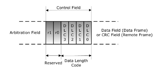
Control Field according to CAN 2.0A
Both bits, r1 and r0, were reserved for future use and were kept at a low (dominant) level.
The Control Field was “re-designed” (CAN 2.0B) as shown in the following image in order to support co-existence of 11- and 29-bit identifiers on the same CAN bus.

Control Field according to CAN 2.0B
A low (dominant) IDE bit indicates an 11-bit message identifier, a high (recessive) IDE bit indicates a 29-bit identifier.
Standard Format: 11 Bit message identifier:
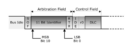
A low (dominant) IDE bit indicates an 11-bit message identifier.
Extended Format: 29 Bit message identifier:
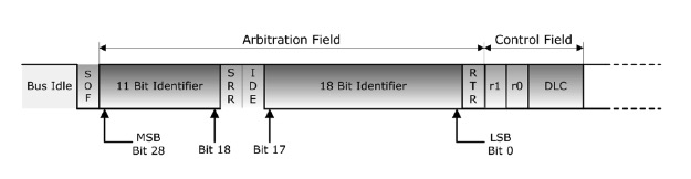
A high (recessive) IDE bit indicates a 29-bit identifier.
The 29-bit message identifier consists of the regular 11-bit base identifier and an 18-bit identifier extension. Between the SOF (Start of Frame) bit and the end of the 11-bit (base) message identifier, both frame formats, Standard and Extended, are identical.
Following the 11-bit base identifier, the Extended Format uses an (always recessive) SRR (Substitute Remote Request) bit, which, as its name implies, replaces the regular RTR (Remote Transmission Request). The following IDE (Identifier Extension) bit is also kept at a recessive level.
With the use of a recessive SRR plus a recessive IDE bit it is guaranteed that standard message frames (11-bit identifier) will always have higher priority than extended message frames (29-bit identifier) with identical 11-bit base identifier (see also Chapter 6 - Bus Arbitration).
The Control Field of an extended message frame, following the 18-bit extended identifier plus RTR bit, has the format of the original CAN 2.0A standard.

Arduino-Due-Based SAE J1939 Programming Kit - Standard Edition
Unleash the power of the Arduino Due with ARM Cortex-M3 processor to develop and test your SAE J1939 application, may it be an SAE J1939 to USB protocol converter, an SAE J1939 Bridge, an SAE J1939 data monitor, and many more. The SAE J1939 Programming Kit comes with many programming samples, including a full-blown SAE J1939 protocol stack (ARD1939).
The included SAE J1939 Simulator Board serves as a transmitter and receiver of SAE J1939 data frames (PGNs). Use the Windows-based jCOM1939 monitoring and simulation software to display, record, or transmit J1939 PGNs, including data request messages. To top things up, the kit includes two books on the SAE J1939 Standard and Arduino Programming for J1939 applications.
While the book's focus is on the Arduino Uno and Mega 2560, the documentation also applies to our SAE J1939 protocol stack for the Arduino Due.