Blog
Recent Posts
SAE J1939 Standards Collection - Serial Control And Communications Vehicle Network
Posted by on
The following is an excerpt from A Comprehensible Guide To J1939 by Wilfried Voss.
The J1939 Standards Collection was designed to follow the ISO/OSI 7-Layer Reference Model as far as necessary. Each layer is addressed by a corresponding document.
The SAE has named documents addressing the transport (4), session (5), and presentation (6) layer in the ISO/OSI 7-Layer Reference Model.
These layers are, however, not documented (in all consequence, they are not necessary for J1939) and thus, the corresponding documents have not been created.
Additional documents with a /0x suffix, such as J1939/01 and J1939/02, identify the industry or application. J1939/81 does not refer directly to any of the seven layers and is regarded as an additional function affecting all layers.
As the name (J1939 Standards Collection) implies, the J1939 standard comprises of several documents:
| Document | Description |
| J1939 | Recommended Practice for a Serial Control and Communications Vehicle Network |
| J1939/01 | Recommended Practice for Control And Communications Network for On-Highway Equipment |
| J1939/02 | Agricultural and Forestry Off-Road Machinery Control and Communication Network |
| J1939/11 | Physical Layer - 250k bits/s, Twisted Shielded Pair |
| J1939/13 | Off-Board Diagnostics Connector |
| J1939/15 | Reduced Physical Layer, 250k bits/sec, Un-Shielded Twisted Pair (UTP) |
| J1939/21 | Data Link Layer |
| J1939/31 | Network Layer |
| J1939/71 | Vehicle Application Layer |
| J1939/73 | Application Layer - Diagnostics |
| J1939/74 | Application - Configurable Messaging |
| J1939/75 | Application Layer - Generator Sets and Industrial |
| J1939/81 | Network Management |
In all consequence, the only documents needed to understand the protocol features are:
| J1939/21 | Data Link Layer |
| J1939/81 | Network Management |
The information in this book is based on these documents.
SAE J1939
The full name of the document is “SAE J1939 Recommended Practice for a Serial Control and Communications Vehicle Network”. This document represents the top level of several documents known as the J1939 Standards Collection. It references to the OSI 7-Layer Model and the corresponding documents and provides a “J1939 Tutorial”. The bulk of the document, though, is comprised of 300+ pages containing data such as Parameter Group Assignments (Appendix A), Address and Identity Assignments (Appendix B) and Fault Reporting Parameters (Appendix C).
Without these appendixes, the document is a mere 19 pages long, where the first 7 pages have filled the table of content, definitions, and abbreviations. Also, a considerable amount of information, especially about the J1939 message format, is repeated in a different form in SAE J1939/21. Some references to the J1939 Network Management are in stark contrast to SAE J1939/81.
SAE J1939/11 Physical Layer
The physical layer of J1939 is based on Controller Area Network (CAN) as described in ISO11898. J1939-11 specifies a shielded twisted pair wire with a maximum length of 40 m (roughly 120 ft.). The CAN baud rate is 250 Kbit/sec per standard. The maximum number of ECUs is limited to 30 for one segment. Several units may be connected using unique interconnection ECUs.
SAE J1939/11 is an abbreviated version of ISO11898 or the Bosch CAN specification, respectively, with some added electrical specifications for use in vehicles. The CAN Bus specifics have been wrecked to a useless degree.
SAE J1939/13 Off-Board Diagnostic Connector

SAE J1939/13 defines a standard connector for diagnostic purpose.
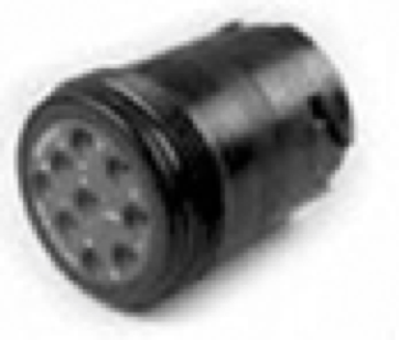
The connector is a Deutsch HD10 - 9 – 1939 (9 pins, round connector).
SAE J1939/15 Reduced Physical Layer
SAE J1939/15 describes a physical layer that utilizes an Unshielded Twisted Pair (UTP) cable.
SAE J1939/21 Data Link Layer
SAE J1939/21 defines the use of the CAN data frame (29-bit identifier, Parameter Group Numbers – PGN, etc.) and the transport protocol functions, i.e. a definition of how messages longer than the standard CAN data length (8 bytes) are transmitted in a J1939 bus network.
As in the SAE J1939/11 standard, any references to CAN specifics have been wrecked to a useless degree.
Without further ado, the J1939/21 standard, assuming that the reader has already studied all relevant publications and knows what Parameter Groups are, jumps immediately into the detailed architecture of Parameter Group Numbers. It is like explaining the function of an automobile by starting with the details of the gas injection system. The document is poorly written and lacks any structure.
For instance, the mere fact that some J1939 messages may be longer than the standard CAN message of 8 bytes is mentioned in numerous chapters without offering any substantial details on how the messages are packetized. In the same spirit, topics like, for instance, PDU Formats are explained repeatedly, spanning over several chapters.
SAE J1939/31 Network Layer
SAE J1939/31 describes the services and functions needed for intercommunication between different segments of a J1939 network by means of bridges, routers, gateways, and repeaters.
SAE J1939/71 Vehicle Application Layer
SAE J1939/71 describes and defines the Parameter Group Numbers and Suspect Parameter Numbers. This document is updated very frequently to incorporate new standard parameters and messages.
Parameters groups are, for instance, engine temperature, which includes coolant temperature, fuel temperature, oil temperature, etc. Parameter Groups and their numbers (PGN) are listed in SAE J1939 (roughly 300 pages) and defined in SAE J1939/71, a document containing roughly 800 pages filled with parameter group definitions plus suspect parameter numbers (SPN).
Despite reasonable expectations, the SAE J1939/71 standard lacks any explanation what Program Groups (and their numbers) and Suspect Parameters (and their numbers) are.
SAE J1939/73 Application Layer - Diagnostics
SAE J1939/73 defines functions and messages for accessing diagnostic and calibration data. There are several predefined Diagnostic Messages (DM) used for:
- Reading and writing to ECU memory
- Reporting diagnostic information when running
- Identification of lamp status
- Reading and clearing Diagnostic Trouble Codes (DTCs)
- Start/stop broadcast DMs
SAE J1939/74 Application – Configurable Messaging
SAE J1939/74 describes the message structure for a set of messages that enable the user to determine and announce the parameter placement within a particular message.
SAE J1939/75 Application Layer – Generator Sets and Industrial
SAE J1939/75 describes the parameters and parameter groups predominantly associated with monitoring and control generators and other driven equipment for electric power generation as well as industrial applications.
SAE J1939/81 Network Management
Network Management under SAE J1939 is primarily represented by the Address Claiming Process. While other higher layer protocols based on Controller Area Network (CAN) do not support dynamic node address assignments per default, the SAE J1939 standard provides this ingeniously designed feature to uniquely identify ECUs and their primary function.
SAE J1939-81 provides information about the architecture of an ECU Name and how the ECU claims an addressing using that Name. The Name is a 64 bit (8 bytes) long number giving every ECU a unique identity.
SAE J1939 ECU Simulator Board With USB Port
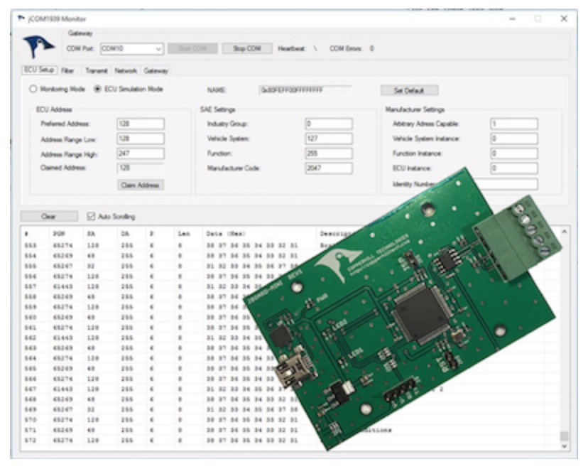
The jCOM.J1939.USB gateway board is a high-performance, low-latency vehicle network adapter for SAE J1939 applications. It allows any host device with a USB COM port to monitor SAE J1939 data traffic and communicate with the SAE J1939 vehicle network.
The board supports the full SAE J1939 protocol according to J1939/81 Network Management (Address Claiming) and J1939/21 Transport Protocol (TP). It is also supported by an extensive programming interface for Windows and Linux/Ubuntu applications, including full C/C++/C# source code for short time-to-market developments.
The strength of the board lies in the fact that the entire SAE J1939 protocol, including all timing requirements, is stored on-chip, thus taking the burden off the main system. The board uses a USB COM port to communicate with the main system, i.e. all data transfer is handled through a standard COM port access.
The communication protocol between the board and the main system is well documented and thus allows a porting to any computer system with a USB connection. Working source code libraries exist for Windows (C# under Visual Studio 2012/2013), Linux and its derivatives (C++ using Code::Blocks), and Raspberry Pi (C using the standard gcc compiler).
Guide To SAE J1939 - Address Claiming Procedure Overview
The following is an excerpt from A Comprehensible Guide To J1939 by Wilfried Voss. While other higher layer protocols based on the CAN Bus do not support dynamic node address assignments per default, the SAE J1939 standard provides yet another ingeniously designed feature to uniquely identify ECUs and their primary function.Note: The CAN standard in itself does not support node (ECU) addresses, only [...]
SAE J1939 Programming with Arduino - SAE J1939/81 - Address Claim Procedure
This post is part of a series about SAE J1939 ECU Programming & Vehicle Bus Simulation with Arduino. Network Management under SAE J1939 is primarily represented by the Address Claiming Process. While other higher layer protocols based on Controller Area Network (CAN Bus) do not support node address assignments per default, the SAE J1939 protocol provides yet another ingeniously designed [...]
SAE J1939 Address Claim Procedure - SAE J1939/81 Network Management
Network Management under J1939 is primarily represented by the Address Claiming Process. While other higher layer protocols based on Controller Area Network (CAN) do not support dynamic node address assignments per default, the SAE J1939 standard provides this ingeniously designed feature to uniquely identify ECUs and their primary function. SAE J1939/81 prefers the use of CA (Controller Application) rather than ECU [...]
 Loading... Please wait...


