 Loading... Please wait...
Blog
Recent Posts
ESP32 UART0, UART1, UART2 Access Using the Arduino IDE
Posted by on
In the following, I am using the ESP32 WROOM Devkit for this tutorial in combination with the Arduino IDE. For more information on programming the ESP32 using the Arduino IDE, please refer to “Getting started with ESP32 development board and Arduino.”
The Arduino IDE uses the Serial class (assigned to UART0) to access the USB port on the ESP32 WROOM Devkit. It is suitable for posting debugging information on the IDE’s Serial Monitor. However, the ESP32 offers more options for serial communication.
ESP32 UART Interfaces
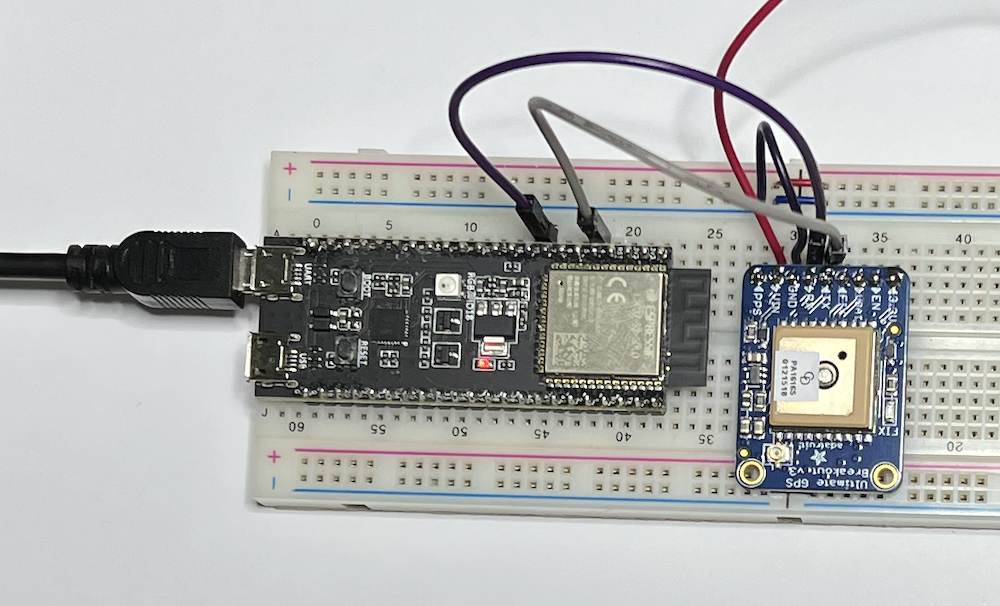
The ESP32 has three UART interfaces: UART0, UART1, and UART2. They provide asynchronous, bidirectional communication at up to five Mbps. You can establish serial protocols using the appropriate breakout boards, such as RS232, RS422, RS485, USB, and more. One advantage of using the ESP32 is that you can assign almost any pin to the TX and RX signals for any serial port. Some development boards may come with labels such as RX2 and TX2, but you can still assign them to other pins.
However, when working with the ESP32 using the Arduino IDE, you will notice that the Serial class works fine, but Serial1 and Serial2 will not. Consequently, accessing Serial1 and Serial2 on the ESP32 requires using the HardwareSerial library.
Programming with the HardwareSerial Class
- Baud Rate
- UART Mode
- Rx Pin
- Tx Pin
As I mentioned before, you can assign almost any pin to the TX and RX signals for any serial port but there are some restrictions: Any GPIO pin can serve as Serial RX, but only the ones between GPIO0 and GPIO31 can be used as TX.
The HardwareSerial class supports all methods used for the standard Serial class, such as read(), write(), and more.
Addressing Potential Serial Buffer Overflow
I worked on numerous embedded projects that required bidirectional serial data exchange. I learned quickly that data reception can easily result in a buffer overflow unless you take protective actions through proper code design. The exact result of a buffer overflow is unpredictable, but it will most likely result in a program crash.
Before using the ESP32 as my standard solution, I worked with other embedded systems based on the NXP LPC17xx processors in combination with the LPCXpresso IDE. This setup required the development of code that operated closer to the hardware layer than using the Arduino IDE. Regarding the serial connection, I was able to use an Interrupt Service Routine (ISR) to catch every received data byte and store it in a buffer. I designed the buffer to prevent overflow effectively by assigning a sufficient buffer size and using a ring buffer algorithm.
Unfortunately, the Arduino programming environment does not provide an easy means of creating a similar protection against buffer overflow. Like the previously referred method, the Arduino/ESP23 processors receive serial data per interrupt routine. However, I consider the default buffer size insufficient for most serial-interface applications.
The standard Arduino processor provides 64 bytes, while the ESP32 has 256 bytes per default. For instance, a GPS sensor with NMEA 0183 protocol easily exceeds that size within milliseconds.
The standard buffer size will be sufficient when you can guarantee an adequate data polling frequency. However, you may encounter infrequent processor crashes when the buffer size is exceeded by only one byte. I observed this effect with the ESP32 but have not tested it with Arduino processors.
The thought that comes to mind is creating our own ISR and implementing a sufficient buffer algorithm. I don’t know if such an approach is possible, but it will require more knowledge and time than I am willing to invest. One resource warned about adding an ISR to the existing routine as it may create unpredictable results (i.e., program crashes).
You can, however, adjust the buffer size by using the setRxBufferSize method, as demonstrated in the sample code below. The ESP32 has more than sufficient memory resources to accommodate large buffer sizes. Nevertheless, keep an eye on the data polling frequency.
ESP32 UART Access Programming Sample
The sample code below is very simple, so I don’t provide a download link.


espBerry - ESP32 Development Board with Dual Isolated CAN Bus HAT
The espBerry DevBoard combines the ESP32-DevKitC development board with any Raspberry Pi HAT by connecting to the onboard RPi-compatible 40-pin GPIO header.
The Dual Channel CAN Bus expansion HAT, designed for the Raspberry Pi, supports the full CAN2.0 Standard, and it features multi onboard protection circuits, high anti-interference capability, and reliable operation. As a result, it suits applications such as automotive devices or industrial automation.
The HAT is well documented, and there are multiple code samples using the C programming language under the Arduino IDE.
espBerry Project: ESP32 with CH9102F USB-UART Chip
I have a project that involves the ESP32-DevKitC development board where the application requires the fast transport of data per USB. The onboard USB-UART bridge chip provides transfer rates of up to 3 Mbps. In addition, the ESP32 has three UART interfaces, i.e., UART0, UART1, and UART2, which provide asynchronous communication, communicating at a speed of [...]