Blog
Recent Posts
Essential Resources for NMEA 2000 Development with ESP32
Posted by on
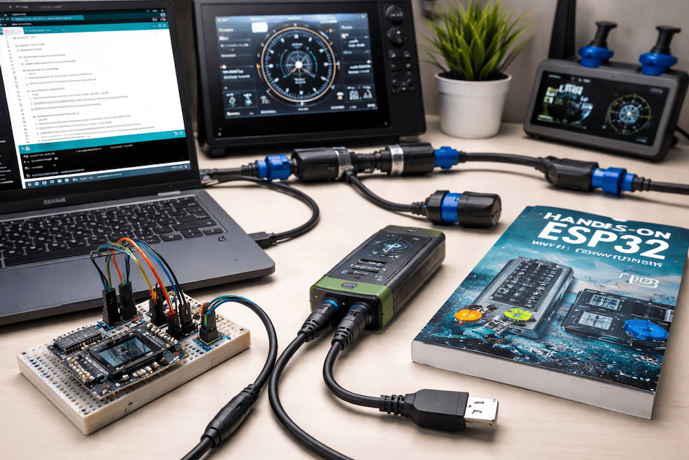
 This blog post is intended to highlight additional, practical resources that can significantly improve the development workflow for NMEA 2000 devices based on the ESP32 processor. Once the fundamentals of CAN bus and NMEA 2000 are understood, progress often depends on having the right reference material and the right diagnostic tools. The following resources address two common challenges in ESP32-based marine development: writing reliable firmware and validating CAN traffic during testing and integration.
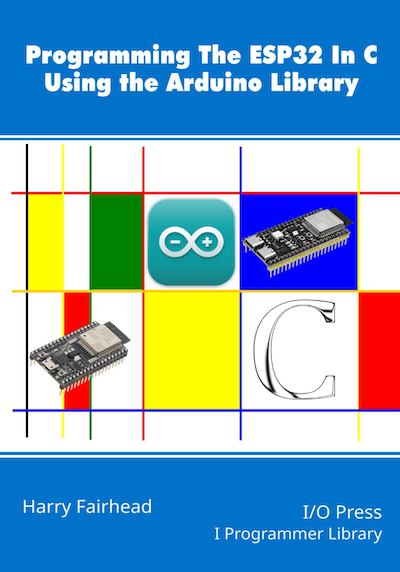
A dedicated book on ESP32 programming with the Arduino IDE is an especially valuable companion for NMEA 2000 development. While NMEA 2000 defines how data is exchanged on the CAN bus, the quality and reliability of a device ultimately depend on how well the microcontroller firmware is written. A practical ESP32 book helps developers understand the Arduino programming model, ESP32-specific features, memory management, task handling, and peripheral control. These skills translate directly to NMEA 2000 applications, where timing, stability, and clean CAN message handling are critical. By building confidence in ESP32 programming, the book reduces development time and lowers the risk of subtle bugs that can lead to unstable network behavior.
Programming the ESP32 In C Using the Arduino Library is an excellent introduction to the ESP32 and a resource we strongly recommend for NMEA 2000 and embedded development projects. It explains why the ESP32 is both inexpensive and powerful, and shows how to program it efficiently in C using the Arduino IDE layered on top of Espressif’s official development framework. The book focuses on building real skills rather than finished projects, covering GPIO, interrupts, PWM, SPI, I²C, UARTs, Wi-Fi, sensors, motors, power management, and FreeRTOS. By emphasizing core concepts and hands-on understanding, it equips readers to confidently design, debug, and complete their own ESP32-based applications with far less trial and error. More information...
Note: We are aware that there are many books covering ESP32 programming with the Arduino IDE. However, we consider this title the closest match to our topic, as it focuses on core concepts and fundamentals rather than narrowing its scope to specific application use cases.
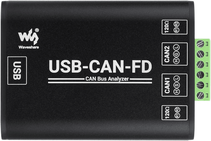
Waveshare Industrial Grade CAN/CAN FD Bus Data Analyzer
A USB-to-CAN or CAN FD adapter is equally important for serious NMEA 2000 development. While an ESP32 can transmit and receive CAN frames, debugging without external visibility is difficult and often frustrating. A CAN adapter allows developers to monitor live bus traffic, inspect raw frames, verify PGNs, and confirm correct arbitration, timing, and data formatting. It also enables controlled testing by injecting messages or simulating other devices on the network. Even though NMEA 2000 itself uses classic CAN, a CAN FD–capable adapter offers flexibility and long-term usefulness for broader CAN-based projects beyond marine applications.
The Waveshare USB-CAN-FD adapter is an industrial-grade, high-performance USB-to-CAN and CAN-FD adapter designed for reliable bus communication, analysis, and diagnostics. It features two independent CAN-FD interfaces with electrical isolation and comprehensive protection circuitry, ensuring stable operation in demanding development and test environments.
The adapter supports Windows XP, 7, 8, 10, and 11 and is supplied with drivers, CAN-FD tools, example applications, and development documentation. Connected to a PC or industrial controller via USB, it enables real-time CAN and CAN-FD message transmission, monitoring, logging, and protocol analysis. Its compact form factor and straightforward operation make it well suited for learning, debugging, and validating CAN-based systems, as well as for integration into industrial automation, power systems, and intelligent control applications that rely on CAN or CAN-FD communication. More information...
For more technical details, see the Waveshare Wiki
Note: As with our choice of literature, there are many alternative devices available. However, we found the Waveshare adapter to offer an excellent balance between functionality and price. If you consider other options, make sure the device includes robust CAN data analyzer software for Windows, Linux, or both, as this is essential for effective development and debugging.
Together, a solid ESP32 programming reference and a reliable CAN analysis tool form a powerful development foundation. The book strengthens firmware design and implementation, while the CAN adapter provides transparency into network behavior. For anyone developing NMEA 2000 devices with the ESP32, these resources help move projects from experimentation to professional, predictable results.
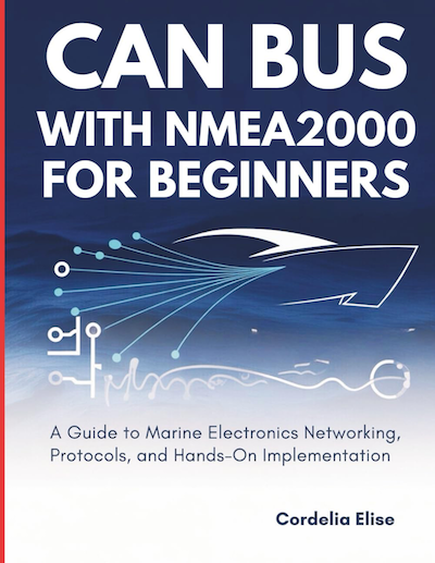
Modern marine electronics rely on NMEA 2000, a standardized CAN-based network that allows engines, sensors, displays, navigation systems, and monitoring devices to communicate over a single, shared backbone. Instead of point-to-point wiring, NMEA 2000 uses a robust two-wire CAN bus to distribute data efficiently and reliably across the vessel. While powerful and flexible, this technology often appears intimidating due to unfamiliar terminology, strict wiring rules, and a lack of clear beginner-level explanations.
Many boat owners, technicians, and engineers struggle to understand how CAN Bus and NMEA 2000 systems actually work in practice. Confusing diagrams, fragmented documentation, and overly theoretical explanations make it difficult to build or troubleshoot a network with confidence. That is exactly why First Steps in CAN Bus with NMEA 2000 was written. This book provides a beginner-friendly yet technically accurate path to understanding, designing, and maintaining NMEA 2000 networks without requiring prior CAN experience.
Whether you are new to marine electronics or looking to strengthen your foundation before moving on to advanced configurations, this guide walks you through every critical concept step by step. It explains how CAN communication works, how NMEA 2000 builds on it, and how real devices share data on the network. Rather than acting as a dry reference manual, the book emphasizes practical understanding through real-world examples, clear diagrams, and straightforward explanations.
Inside the book, you will learn how to design a stable network using correct cabling and termination practices, manage power and grounding to avoid common failures, understand PGNs and data flow, and safely integrate displays, sensors, GPS units, and engine gateways. Dedicated chapters focus on troubleshooting and testing, showing how to diagnose voltage issues, communication errors, and network load problems using practical methods that reflect real installations.
Written with field-tested experience and a clear, professional voice, First Steps in CAN Bus with NMEA 2000 turns a complex marine communication standard into something practical and approachable. It gives you the knowledge and confidence to design, install, and maintain reliable NMEA 2000 networks, helping your systems perform as intended and saving time, frustration, and costly mistakes along the way. More information...
Free SAE J1939 Protocol Stack for ESP32 — Open New Paths for CAN Bus Innovation
We at Copperhill Technologies are excited to announce that we are releasing a fully functional SAE J1939 protocol stack for the ESP32 — and best of all, it’s completely free to use. Whether you’re an engineer, a student, or a maker, this opens up serious possibilities for CAN-bus projects and vehicle network applications — without [...]
ESP32 for CAN Bus Application Developments
The ESP32 has become one of the most versatile microcontrollers in modern embedded development. With its dual-core processor, integrated Wi-Fi and Bluetooth, and robust peripheral set, it is a natural fit for advanced networking and control applications. One of its rising uses is in Controller Area Network (CAN Bus) systems, where the ESP32 provides both [...]
Comparing Embedded System Choices for CAN Bus: Arduino, Teensy, and ESP32
At Copperhill Technologies, we frequently receive inquiries asking us to recommend the “best” embedded system for CAN Bus applications. It’s a fair question, but unfortunately, there is no universal answer. The choice depends heavily on a user’s technical knowledge, development experience, and—most importantly—the specific requirements of their application. Instead of prescribing a one-size-fits-all solution, we would [...]
Unlock the Future of Marine Apps with the ESP32-S3 CAN Bus Board with NMEA 2000 Connector
As the marine industry continues to embrace smart technologies, there's a growing demand for powerful, connected, and reliable embedded solutions that can handle everything from engine diagnostics to GPS data aggregation. Whether you're building a marine monitoring system, an onboard data logger, or an intelligent control unit, you need a development board that offers high [...]
Build Smarter Interfaces: ESP32-S3 with 4” Display, Wi-Fi, Bluetooth & CAN FD
Looking to build an advanced HMI, diagnostic tool, or industrial control panel with cutting-edge connectivity and sleek graphics? Meet our ESP32-S3 4" 480x480 IPS LCD Board, a powerhouse designed for developers and engineers who demand performance, versatility, and ease of integration. Feature-Packed for Modern Applications At the heart of this board is the Espressif ESP32-S3-WROOM-1U-N16R8, a powerful [...]
CAN Bus Development for Embedded Systems: With and Without an Operating System
The Controller Area Network (CAN) Bus has become an essential communication protocol in automotive, industrial, marine, and robotics applications due to its robustness, efficiency, and real-time capabilities. When it comes to embedded systems, developers have multiple hardware and software platforms to choose from—some with full operating systems (OS), others running bare-metal (without OS). At Copperhill Technologies, [...]
Introducing the ESP32 with Dual Isolated CAN Bus Port
The ESP32 Development Board is renowned for its versatility, boasting features like Wi-Fi, Bluetooth, and ample processing power. When combined with the Dual Isolated CAN Bus HAT, it transforms into a formidable tool for CAN bus communication. Key Features: Dual CAN Channels: Facilitates simultaneous communication over two separate CAN networks. Galvanic Isolation: Each CAN channel is electrically isolated, [...]
The ESP32 Processor and Programming MCP2515 and MCP2517/18 Per SPI Port
Introduction The ESP32 is a powerful, low-cost microcontroller developed by Espressif Systems, widely used in IoT applications. It features integrated Wi-Fi and Bluetooth, making it a popular choice for embedded systems. Among its various interfaces, the Serial Peripheral Interface (SPI) plays a crucial role in facilitating communication with peripherals such as sensors, displays, and external memory [...]
 Loading... Please wait...


