 Loading... Please wait...

Blog
Recent Posts
Developing High-Performance CAN FD Applications with the Microchip dsPIC33CK256MP502
Posted by on
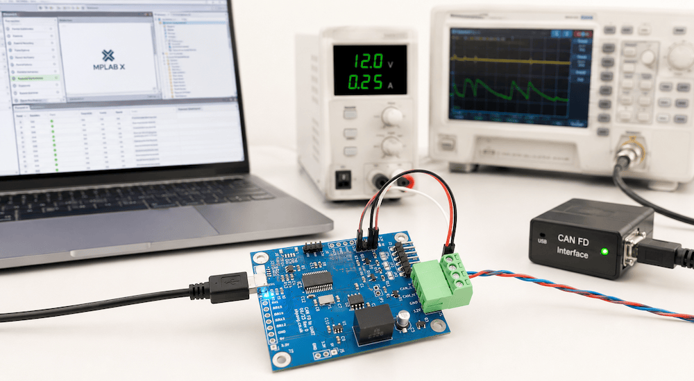 CAN FD has become an important option for embedded systems that have outgrown the limitations of Classical CAN but still require the reliability, deterministic behavior, and straightforward network architecture that have made CAN so successful.
For developers working with real-time control, sensor processing, motor control, industrial equipment, or automotive electronics, the challenge is often not simply adding CAN FD communication. The processor must handle the network while simultaneously performing time-critical application tasks.
The Microchip dsPIC33CK256MP502 provides an interesting solution by combining a high-performance Digital Signal Controller (DSC) with an integrated CAN FD controller.
The Microchip dsPIC33CK256MP502 CAN FD Demo Board provides a compact platform for evaluating this combination and developing practical CAN FD applications.
From Classical CAN to CAN FD
Classical CAN remains one of the most widely used embedded networking technologies. However, its 8-byte maximum data payload and relatively limited data throughput can become restrictive as embedded systems exchange increasing amounts of information.
CAN FD, or CAN with Flexible Data Rate, extends the original CAN protocol in two particularly important ways.
First, a CAN FD data frame can contain up to 64 data bytes, compared with the 8-byte maximum of Classical CAN.
Second, CAN FD allows the data portion of the message to operate at a higher bit rate than the arbitration portion. A network can therefore retain CAN's familiar arbitration mechanism while transmitting the actual payload considerably faster.
The result is increased network throughput without abandoning the basic principles that make CAN attractive for embedded and real-time applications.
The dsPIC33CK256MP502
At the center of the demo board is Microchip's dsPIC33CK256MP502, a 100 MHz, single-core Digital Signal Controller.
The device combines conventional microcontroller functionality with a DSP engine designed for computationally demanding real-time applications. It includes:
-
256 KB Flash memory
-
24 KB RAM
-
Integrated CAN FD controller
-
High-speed ADC capabilities
-
PWM peripherals
-
UART, SPI, and I²C communications
-
DSP-oriented processing capabilities
-
Peripherals designed for real-time control applications
This combination makes the processor particularly attractive when CAN FD communication is only one part of a larger embedded application.
For example, a device might acquire analog information from sensors, perform calculations or filtering, control an actuator, and communicate the resulting data with other devices over CAN FD.
Integrated CAN FD
One important advantage of the dsPIC33CK256MP502 is that the CAN FD controller is integrated directly into the processor.
The controller supports Classical CAN 2.0B as well as CAN FD, allowing developers to use the same processor platform for applications ranging from conventional CAN networks to higher-throughput CAN FD systems.
The CAN FD peripheral provides features such as configurable transmit and receive FIFOs, message filtering, a transmit queue, transmit-event handling, timestamps, and programmable retransmission behavior.
These hardware resources can reduce the amount of software intervention required for routine CAN communication and allow the processor to concentrate on the application itself.
A Ready-to-Use CAN FD Development Platform
Working with a CAN-capable processor alone still requires supporting hardware before it can communicate with a physical CAN network. A CAN controller operates at the protocol level, while a CAN transceiver provides the electrical interface to the CAN bus.
The Microchip dsPIC33CK256MP502 CAN FD Demo Board combines the processor with an onboard CAN FD transceiver, creating a compact development platform that can be connected directly to a CAN or CAN FD network.
The board accepts an 8 to 24 VDC supply and includes reverse-polarity protection, making it convenient for bench development as well as experiments using power sources representative of real embedded systems.
Additional hardware includes an RGB status LED and a UART interface with selectable 3.3 V or 5 V logic levels.
Starting with Working CAN FD Communication
A development board becomes considerably more useful when developers do not have to start by writing every peripheral driver from scratch.
The board is supplied with demonstration firmware configured for a 500 kbit/s nominal arbitration rate and a 2 Mbit/s CAN FD data rate.
An MPLAB X project using Microchip MCC Melody provides the starting point for application development.
This allows developers to begin with working CAN FD communication, study the configuration, and then modify the project for their own message formats, timing requirements, filters, data rates, and application functions.
An optional bootloader is also available.
Adding Sensors and Peripherals Through Qwiic
The board also includes an I²C/Qwiic connector.
Qwiic provides the standard I²C signals together with 3.3 V power and ground through a polarized four-pin connector. A wide range of compatible sensors, displays, memory devices, I/O expanders, and other peripherals can therefore be added without creating additional interface circuitry for an initial prototype.
This creates an especially useful architecture for CAN FD experimentation:
Sensor or peripheral → dsPIC33CK256MP502 → CAN FD network
A developer could, for example, connect a temperature, pressure, motion, or other sensor through I²C, process its readings with the dsPIC33, and transmit the resulting information over CAN FD.
Conversely, CAN FD messages received from the network could be used to control peripherals connected to the processor.
More Than a CAN FD Interface
The dsPIC33CK256MP502 is particularly interesting because the processor is capable of much more than simply sending and receiving CAN frames.
Its architecture is intended for demanding real-time applications such as motor control, digital power conversion, sensor processing, and other applications requiring deterministic processing.
That makes the board useful for experimenting with designs in which CAN FD becomes the communications component of a larger control system.
Possible applications include:
-
Industrial controllers
-
Distributed sensor systems
-
Motor-control nodes
-
Automotive and vehicle electronics
-
Robotics
-
Test equipment
-
Data-acquisition systems
-
Embedded gateways
-
CAN FD protocol development
-
Educational and laboratory projects
The same board can also serve as a convenient platform for learning the differences between Classical CAN and CAN FD without immediately developing custom hardware.
CAN FD as a Path Beyond Classical CAN
CAN FD does not replace Classical CAN in every application. An 8-byte payload and conventional CAN bit rates remain entirely adequate for many embedded networks.
However, applications increasingly need to exchange larger amounts of information while maintaining the proven arbitration and error-handling concepts of CAN.
CAN FD provides a logical migration path.
For embedded developers, the dsPIC33CK256MP502 adds another advantage: CAN FD communication can be combined with substantial real-time processing capability in a single device.
The result is a platform suitable not only for demonstrating CAN FD frames but for developing complete embedded nodes in which communication, sensing, processing, and control are tightly integrated.
Microchip dsPIC33CK256MP502 CAN FD Demo Board
The Microchip dsPIC33CK256MP502 CAN FD Demo Board provides the essential hardware needed to begin experimenting with this architecture, including the dsPIC33CK processor, CAN FD physical interface, power supply circuitry, UART access, status indication, and I²C/Qwiic expansion.
With demonstration firmware and an MPLAB X/MCC Melody project available as a starting point, the board can be used to evaluate CAN FD, develop prototype network nodes, experiment with higher CAN data rates, and explore the dsPIC33CK platform before committing to a custom hardware design.
For specifications, documentation, demonstration software, and ordering information, visit the Microchip dsPIC33CK256MP502 CAN FD Demo Board product page at Copperhill Technologies.

Making Embedded Systems: Design Patterns for Great Software
Interested in developing embedded systems? Because embedded systems operate under tight constraints, they demand a disciplined and efficient approach to programming. This accessible guide introduces proven development practices based on classic software design patterns as well as patterns specific to embedded programming. You’ll learn how to design system architectures around processors rather than operating systems, while developing practical strategies for working with hardware limitations, evolving designs, and manufacturing requirements.
Written by an experienced engineer whose projects range from DNA scanners to children’s toys, this book is ideal for intermediate and experienced programmers working on virtually any embedded platform. This expanded second edition adds new material on IoT and networked sensors, motors and motion, debugging, data-handling strategies, and more.
-
Optimize embedded systems to reduce cost while improving performance
-
Develop robust software architectures for resource-constrained environments
-
Work effectively with sensors, displays, motors, and other I/O devices
-
Reduce RAM usage, power consumption, code size, and processor cycles
-
Learn to interpret schematics, datasheets, and power requirements
-
Implement complex mathematics and machine learning on small processors
-
Design effective embedded systems for IoT and networked sensor applications
CAN FD and SAE J2716 SENT: Automotive Sensor Communication, Testing, and Applications
Modern automotive and industrial control systems rely on several communication technologies, each optimized for different tasks. CAN and CAN FD are widely used for communication between electronic control units, while sensor interfaces such as SAE J2716 SENT provide an efficient way of transferring high-resolution measurements from sensors to those controllers. Combining CAN FD and SENT on [...]
Building a Classical CAN to CAN FD Gateway with the ESP32-S3
As CAN FD continues to replace Classical CAN in automotive, industrial, agricultural, and heavy equipment applications, many engineers face a familiar dilemma: they have one or more perfectly functional Classical CAN devices that cannot simply be connected to a CAN FD network. The obvious solution would be to redesign the existing hardware and rewrite the firmware [...]
Building Wireless CAN Gateways with ESP32-S3
The convergence of wireless networking and CAN bus technology is opening entirely new possibilities for automotive, industrial, agricultural, and embedded systems. Instead of connecting a laptop directly to a CAN network with a USB cable, engineers increasingly want remote access through Wi-Fi, Bluetooth, or Bluetooth Low Energy (BLE). Whether monitoring a machine from across a [...]
Copperhill Technologies Launches an Engineering Community for the Entire SAE J1939 Ecosystem
Copperhill Technologies today announced the expansion of the JCOM1939 Community into a dedicated engineering forum serving professionals across the entire SAE J1939 ecosystem. While the community has traditionally focused on embedded software development, it now welcomes Test & Validation Engineers, Systems Integrators, OEM engineers, hardware developers, technical support specialists, and others involved in designing, integrating, [...]
How to Build a Raspberry Pi CAN-to-Ethernet Gateway
The Controller Area Network (CAN) remains one of the most reliable communication technologies in embedded systems, industrial automation, commercial vehicles, marine electronics, and robotics. At the same time, Ethernet has become the preferred medium for connecting systems over long distances, integrating with cloud services, and providing remote access. Bridging these two worlds is a common requirement [...]
CAN Bus vs. CAN FD: When Is It Worth Upgrading? A Practical Guide for Embedded System Developers
For more than three decades, Classical CAN (Controller Area Network) has been the workhorse of industrial automation, automotive electronics, agricultural machinery, marine systems, and countless embedded applications. It has earned a reputation for exceptional reliability, deterministic communication, and outstanding error detection. Yet the demands placed on embedded networks continue to grow. Today's systems generate far more [...]
How to Build a CAN Bus Prototype Before Designing Your PCB
Modern embedded systems rarely begin with a custom PCB. In fact, the fastest and often the most successful development projects start on inexpensive development hardware that allows engineers to validate concepts, write firmware, and test communication long before the first schematic is finalized. When developing CAN Bus and SAE J1939 applications, I have found that the [...]
Why Embedded Engineers Need Raspberry Pi for CAN Bus Development
The Raspberry Pi has earned its reputation as one of the most versatile embedded computing platforms ever created. Originally introduced as an educational computer, it has evolved into a serious engineering tool used for industrial automation, robotics, automotive development, data acquisition, and IoT applications. For engineers working with CAN Bus and CAN FD networks, adding [...]
Understanding CAN Bus Error Frames: A Practical Guide to Diagnosing CAN Network Problems
When you first connect a new CAN Bus network, everything usually works perfectly—until it doesn't. Your firmware transmits messages, but nothing appears on the network. Your CAN controller reports transmit errors. Suddenly, the node enters Error Passive mode, and eventually Bus Off. Your analyzer may even display Error Frames, but it rarely explains why they occurred. If [...]