Blog
Recent Posts
SAE J1939 Network Bridge With RS232/Wireless Connection
Posted by on
As part of another customer project, we have started work on an SAE J1939 network bridge device, which we call the jCOM.J1939.BRIDGE. The bridging serial hardware layer is RS232 in combination with a bit-stuffing protocol, similar to the protocol described at JCOM.J1939 PROTOCOL & PROGRAMMING INTERFACE (PDF).
Our customer will use the RS232 serial port for extension of the networks per wireless connection, i.e. by means of an RS232-to-wireless gateway.
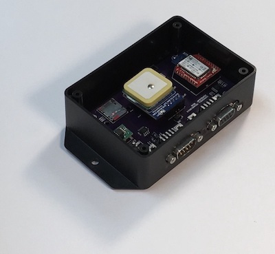
The hardware design is based on our SAE J1939 / OBD-II Electronic Logging Device With Bluetooth (as shown in the image to the left), a generic hardware device we use for a variety of CAN Bus applications (incl. OBD-II and SAE J1939).
According to customer requirements, this current version forwards each received J1939 message frame 1:1 to the other network, i.e. without message filtering or node address mapping, which implies that there can be no node address conflict between both networks. We call this mode “Bridge Level 0,” and the plan is to add higher levels of bridging functionality.

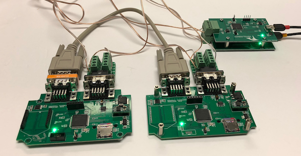
The above image shows the test environment, containing of two jCOM bridging boards, which are connected per RS232 cable plus a null-modem converter.
Both devices are being fed with their own (independent) SAE J1939 data frames using our SAE J1939 ECU Simulator Board With USB Port in combination with our jCOM1939 Monitor, an SAE J1939 Monitoring, Analyzer and ECU Simulation software under Windows.
Future (higher) levels will allow the mapping of ECU source addresses to prevent address collisions between the networks plus message filtering to reduce the serial busload by eliminating SAE J1939 message frames (PGN) that are not needed for the operation.
Also, currently the device supports only a CAN baud rate of 250k bits/sec, but we are in the process of adding a setup mode that allows that allows the user to set 250k, 500k, or automatic detection, with default at 250k.
For further information, please feel free to contact us.
CAN Logger 1000
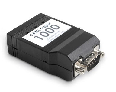
The CANLogger1000 offers simple and user-friendly logging of data from a CAN-Bus without the use of a computer. Data are stored on a standard SD-card in a simple format such that it can be directly loaded into an analysis tool for further post processing. The logged data can be transferred to a PC using a standard mini-USB cable and requires no special software.
For advanced users, the device offers a wide range of configuration possibilities, such as message filtering, down-sampling, automatic bit-rate detection, cyclic-logging, heartbeat signal and runtime logging control. Further, recently added features include the ability to transmit up to 20 custom CAN messages (for use in e.g. OBD-II logging) and a new serial interface letting the logger act as a CAN interface for streaming real-time data (incl. integration with Wireshark via CANvas).
 Loading... Please wait...


