Blog
Recent Posts
Industrial And Military-Strength Galvanically Isolated Classical CAN And CAN FD Breakout Boards
Posted by on
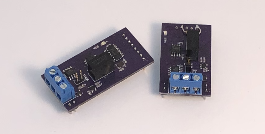
We at Copperhill Technologies are currently developing a new product, the JCOM.CAN.QUAD, a galvanically isolated four-channel CAN-to-USB gateway board. More precisely, two of the interfaces support Classical CAN, while another two operate as CAN FD (Flexible Data Rate) ports. For the sake of maximum flexibility, we decided to use a sandwich design where separate CAN boards (Classical CAN and CAN FD) are soldered onto a main CPU board. That, in turn, allows us to offer the breakout boards as yet another product.
The JCOM.CAN.QUAD gateway board's release date is targeted for March of 2021. We are currently testing both breakout boards. The main objective is to provide sufficient programming resources, specifically for the CAN FD board, since it includes the CAN FD controller (MCP2517FD/MCP2518FD). The release date for both breakout boards is targeted for January 2021.
Galvanic Isolation
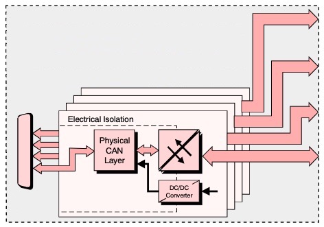
The reading and controlling of multiple CAN Bus connections bares the risk of creating interferences of unpredictable nature. Consequently, we have decided that all CAN channels should be galvanically isolated, not only on the CAN side but also the power supply for each individual power supply as demonstrated in the above picture.
For more information, see: Galvanically Isolated CAN Bus Transceivers Protect Networks Against Destructive Energy...
CAN & CAN FD Breakout Boards
- CAN bus connections on 3-position screw terminal block
- Termination resistor, enabled via pin jumper
- Power and data galvanic isolation
- Activity LED, controlled by GPIO
- RoHS Compliant
- Industrial Temperature Operating Range (-40 to +85 °C)
- CAN FD Only - SPI CAN controller MCP2517FD
- CAN Bus Breakout Board - Size: 1.66" x 1" (42 mm x 25.4 mm)
- CAN FD Breakout Board - Size: 2" x 1" (50.8 mm x 25.4 mm)
CAN Bus Breakout Board
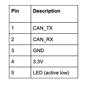
There are two CAN daughter board interfaces. The electrical connections are made via a 5-pin header (0.1” pin pitch). There are two additional 2-pin headers for mechanical support that have no electrical connections. The daughter board will have male pins installed, allowing the daughter boards to be soldered directly to the main board. Alternatively, female headers can be installed on the main board, allowing daughter boards to be added/removed as needed. The headers are spaced to be incompatible with the CAN FD daughter board. The pinout for the 6-pin header is described below.
CAN FD Breakout Board
There are two CAN FD daughter board interfaces. The electrical connections are made via a 8-pin header (0.1” pin pitch). There are two additional 2-pin headers for mechanical support that have no electrical connections. The daughter board will have male pins installed, allowing the daughter boards to be soldered directly to the main board. Alternatively, female headers can be installed on the main board, allowing daughter boards to be added/removed as needed. The headers are spaced to be incompatible with the CAN Bus daughter board. The pinout for the 8-pin header is described below.
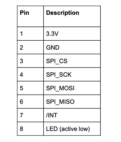
All daughter boards have 3-pin terminal blocks for the CAN bus connection (CAN-H, CAN-L, and GND). Each CAN port has an on-board 120Ω (0.5W) termination resistor. This termination resistor can be connected or disconnected via a pin header. The CAN bus signals are overvoltage protected with 24V bidirectional TVS diodes.
CAN Bus Transceivers
The following CAN transceivers are used:
- CAN: MCP2551
- CAN FD: MCP2562FD
The CAN bus connections are galvanically isolated from the main board. This includes an isolated DC/DC converter to power the CAN transceivers and digital isolators to pass the signals across the isolation barrier.The CAN FD daughter board includes the MCP2517FD SPI CAN controller with 40 MHz crystal.All daughter boards include an activity LED (with current limiting resistor) that is controlled by a GPIO pin on the header. The LED is on when the pin is pulled low.
For further information, please feel free to contact us.
Raspberry Pi 3 B+ System With Dual Isolated CAN Bus Interface
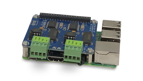
Our Raspberry Pi 3 System With CAN Bus Interface (PiCAN2) comes with a pre-installed Raspbian operating system.
The PiCAN2 DUO ISO board provides two independent isolated CAN-Bus channels for the Raspberry Pi. It uses the Microchip MCP2515 CAN controller in combination with the Texas Instruments ISO1050 isolated CAN transceiver. Connections are made via 4 way screw terminal plugs.
There is an easy-to-install SocketCAN driver, and programming can be accomplished in C or Python.
 Loading... Please wait...

