 Loading... Please wait...
Recent Posts
SAE J1939 ECU Programming & Vehicle Bus Simulation with Arduino - The Arduino Uno And Mega 2560 plus CAN Shield
Posted by on
This post is part of a series about SAE J1939 ECU Programming & Vehicle Bus Simulation with Arduino.

As I had mentioned earlier in this book, it is assumed that you have some basic knowledge of the Arduino Uno and the Mega 2560 itself, Arduino Sketches, and Arduino Shields.

In order to develop and test the sample programs (sketches) as shown in this book, I initially used the Arduino Uno. The hardware consists of an open-source hardware board, usually designed around an 8-bit Atmel AVR microcontroller with 2 KB RAM (working memory), 32 KB Flash Memory (sketches) and 1 KB EEPROM (non-volatile).
These technical specifications are more than sufficient for basic prototyping of CAN Bus and SAE J1939 applications for a proof of concept. However, (and I will repeat this point) with growing demands for execution speed and extended functionality, the Arduino Uno may quickly reach its limits, specifically due to the sparse working memory of 2KB.
In order to overcome the Uno’s memory restrictions (see also my notes on performance restrictions in a later chapter), I also used the Arduino Mega 2560, which, in turn, enabled me to run a full SAE J1939 protocol stack on the Arduino platform.

The Arduino Mega 2560 is a microcontroller board based on the ATmega2560 processor. Compared to the Arduino Uno, it comes (besides a great number of other advancements) with significantly improved memory size, specifically with 8 KB of SRAM compared to the Uno’s 2 KB. In addition, it provides 256 KB Flash Memory (sketches) and 4 KB EEPROM (non-volatile).
In terms of programming, both versions, the Uno and the Mega 2560, are compatible.
Note: All Arduino programs (sketches) as shown in this book were developed and tested with the Arduino Uno and Mega 2560. There is no guarantee that these programs will work “as is” on any other compatible system.
It seems to be an obvious point, but many electronics enthusiasts initially don’t realize that a network requires at least two nodes; otherwise you won’t be able to establish a communication. Unless you have a real-world vehicle network (diesel engine or automobile) available for testing, you will need to buy a second Arduino with CAN shield or you can obtain a commercially available CAN gateway with Windows interface (i.e. a CAN analyzing and monitoring software).
The following image shows my network configuration with the Arduino Uno and Mega 2560 (I actually have several more CAN Bus/J1939 nodes in order to simulate a full vehicle network).

For the network wiring I use regular telephone or speaker wires, which is absolutely acceptable under lab conditions. Just be aware that this kind of wiring may cause problems when connected to an actual vehicle.
For “real-world” cabling, I recommend browsing the Internet for SAE J1939 or ODB-II cables.
Also, in order to assure proper functionality, you should be aware that your network needs to utilize termination resistors as demonstrated in the following image (See also chapter Introduction to Controller Area Network).
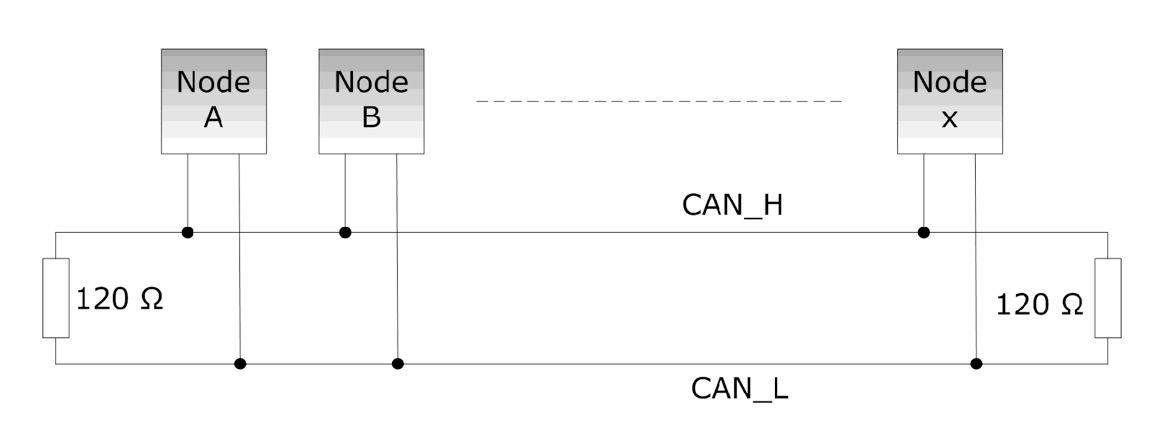
The rule of thumb is to use termination resistors at each end of the network, i.e. a maximum of two resistors. The CAN shields I will introduce in a later chapter have termination resistors on board, but they are not switchable.
When you work with more than two CAN/J1939 nodes (for instance, two Arduinos with CAN shield plus a CAN/J1939 gateway like I do), you need to be aware of the circumstance that you may have more than two termination resistors in the network, which may result in network disruptions. In all consequence, you may have to remove the resistor(s) (Refer to manufacturers’ information on the location and/or removal of the termination resistors).
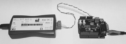
In order to test and verify the proper transmission and reception of CAN messages, I use the ADFweb CAN-to-USB gateway with its Windows interface.
Note: In order to test a CAN/J1939 application, you need at least two CAN/J1939 nodes to establish a network communication. The second node can be another Arduino with CAN shield or (if the budget allows) another CAN/J1939 device with CAN/J1939 data monitoring capabilities.

SAE J1939 has become the accepted industry standard and the vehicle network technology of choice for off-highway machines in applications such as construction, material handling, and forestry machines. J1939 is a higher-layer protocol based on Controller Area Network (CAN). It provides serial data communications between microprocessor systems (also called Electronic Control Units - ECU) in any kind of heavy duty vehicles. The messages exchanged between these units can be data such as vehicle road speed, torque control message from the transmission to the engine, oil temperature, and many more.
A Comprehensible Guide to J1939 is the first work on J1939 besides the SAE J1939 standards collection. It provides profound information on the J1939 message format and network management combined with a high level of readability.