Recent Posts
Guide to SAE J1939 - Transport Protocol (TP) Message Packaging and Reassembly
Posted by on
The following is an excerpt from A Comprehensible Guide To J1939 by Wilfried Voss.
Certain parameter groups may require more than the eight data bytes supported by the CAN standard.
The SAE J1939 standard, namely the Transport Protocol Function, supports message lengths up to 1785 bytes.
If a program group requires more than eight data bytes (9…1785 bytes) and is defined as multi-packet capable, the data will be packaged into a series of CAN Bus data frames.
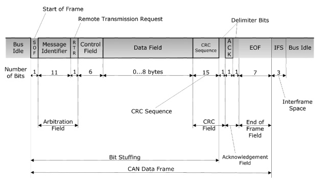
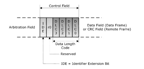
A regular CAN data frame includes a data field of variable length, 0 to 8 bytes. The information indicating the transmitted data length is found in the DLC (Data Length Code) inside the CAN Control Field (See following pictures).


To package CAN messages into a sequence of up to 1785 messages (as well as to re-assemble the CAN frames into one data package), the J1939 Transport Protocol defines the following:
- Each multi-packet message is transmitted using a dedicated Data Transfer PGN (60160, TP.DT = Transfer Protocol Data Transfer); i.e., all message packets will have the same ID.
- The flow control is managed by another dedicated PGN (60146, TP.CM = Transfer Protocol Communication Management).
- The message length must always be 8 bytes (DLC = 8).
- The first byte in the data field contains a sequence number that ranges from 1 to 255.
- The remaining 7 bytes are filled with the data of the original long (> 8 bytes) message.
- All unused data bytes in the last package are being set to FFhex.
The actual total message length is defined by the corresponding Parameter Group (See also chapter Multi-Packet Broadcast).
Using a sequence number plus the remaining seven data bytes yields a total of (255 packages times 7 bytes/package) 1785 bytes per multi-packet message.
The following pictures demonstrate the use of the CAN data field, including the sequence number and the packaging of multiple CAN messages.


The data packages are re-assembled in the order of their sequence number, and the final data package can then be passed to the application layer.
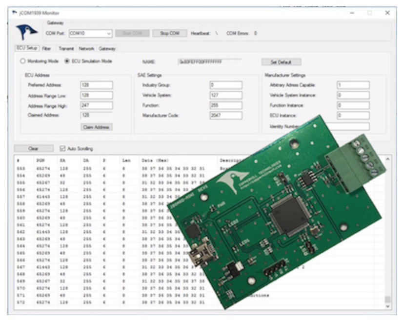
SAE J1939 ECU Simulator Board With USB Port
The jCOM.J1939.USB gateway board is a high-performance, low-latency vehicle network adapter for SAE J1939 applications. It allows any host device with a USB COM port to monitor SAE J1939 data traffic and communicate with the SAE J1939 vehicle network.
The board supports the full SAE J1939 protocol according to J1939/81 Network Management (Address Claiming) and J1939/21 Transport Protocol (TP). It is also supported by an extensive programming interface for Windows and Linux/Ubuntu applications, including full C/C++/C# source code for short time-to-market developments.
The strength of the board lies in the fact that the entire SAE J1939 protocol, including all timing requirements, is stored on-chip, thus taking the burden off the main system. The board uses a USB COM port to communicate with the main system, i.e. all data transfer is handled through a standard COM port access.
The communication protocol between the board and the main system is well documented and thus allows a porting to any computer system with a USB connection. Working source code libraries exist for Windows (C# under Visual Studio 2012/2013), Linux and its derivatives (C++ using Code::Blocks), and Raspberry Pi (C using the standard gcc compiler).
 Loading... Please wait...


