 Loading... Please wait...
Recent Posts
Controller Area Network (CAN Bus) - Message Frame Architecture
Posted by on
The following is an excerpt from A Comprehensible Controller Area Network by Wilfried Voss.

The following chapter explains the CAN message frames by bit and bytes. Further chapters will address the mechanism of message broadcasting, the bus arbitration and the actual physical layer.
In the language of the CAN standard, all messages are referred to as frames; there are data frames, remote frames, error frames and overload frames. Information sent to the CAN bus must be compliant to defined frame formats of different but limited length.
CAN provides four different types of message frames:
- Data Frame – Sends data
Data transfer from one sending node to one or numerous receiving nodes.
- Remote Frame – Requests data
Any node may request data from one source node. A remote frame is consequently followed by a data frame containing the requested data.
- Error Frame – Reports error condition
Any bus participant, sender or receiver, may signal an error condition at any time during a data or remote frame transmission.
- Overload Frame – Reports node overload
A node can request a delay between two data or remote frames, meaning that the overload frame can only occur between data or remote frame transmissions.
The distance between consecutive frames is a minimum of 3 bit times (Interframe Space, see also Chapter 4.5 - Message Frame Format ).
An 11 bit identifier (standard format) allows a total of 211 (= 2048) different messages. A 29 bit identifier (extended format) allows a total of 2 29 (= 536+ million) messages (see also Chapter 4.6 - Extended CAN Protocol).
Both, Data Frame and Remote Frame, are very similar. Basically, the Remote Frame is a Data Frame without the Data Field. Error frames and overload frames have a different format, which will be explained in more detail in a later chapter. In order to explain the various frames and their differences, it is necessary to have a first look into the CAN serial bus bit by bit.
Data And Remote Frames
The following will address data and remote frames and how they, consequently, are distinguished from each other. Both, Data Frame and Remote Frame, are very similar. Basically, the Remote Frame is a Data Frame without the Data Field.
Per definition a CAN data or remote frame has the following components:
- SOF (Start of Frame) - Marks the beginning of data and remote Frames
- Arbitration Field – Includes the message ID and RTR (Remote Transmission Request) bit, which distinguishes data and remote frames
- Control Field – Used to determine data size and message ID length
- Data Field – The actual data (Applies only to a data frame, not a remote frame)
- CRC Field - Checksum
- EOF (End of Frame) – Marks the end of data and remote frames

CAN Data Frame Architecture
The following images shows the CAN frame in more detail:
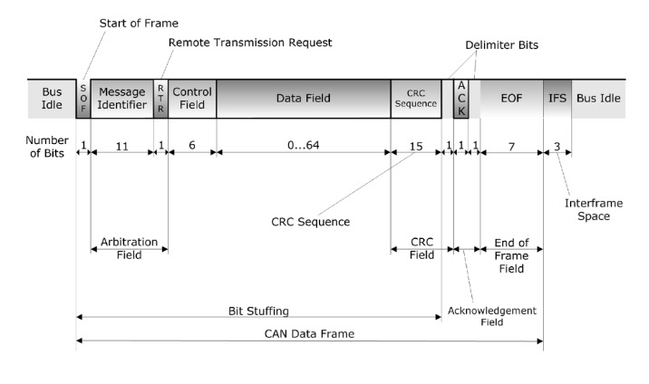
Detailed CAN Data Frame Architecture
Each CAN message starts with a “Start of Frame” bit (SOF), followed by the message identifier and the “Remote Transmission Request” bit (RTR). This particular bit, the RTR bit, is now the focus in explaining the difference between a Data Frame and a Remote Frame, which are both very similar.
Data Frame
A Data Frame broadcasts a message, the actual data, to the CAN bus, either due to change of an event (for example, the change of an input signal, a timer event, etc.) or as a response to a message request. The data frame, identified by a unique message ID, may be accepted by any number of nodes in the network according to the individual application needs, but can only be transmitted by the (one and only) node associated with the data message.

RTR in a Data Frame
Between the Start of Frame (SOF) bit and the end of the message identifier, both frames, Data Frames and Remote Frames, are absolutely identical. A Data Frame is detected by a low (dominant) RTR (Remote Transmission Request) bit. Each receiving node in a CAN network, when detecting a low RTR bit, will now know that the received message is a Data Frame. In fact, the RTR bit is part of the arbitration portion of a message frame.
Note: The remote frame and the requested data frame use the same message identifier (see also Chapter 4.4 - Remote Frame). Both frames are distinguished by the RTR (Remote Transmission Request) bit, which is part of the arbitration field. In case a data frame and a remote frame using the same message ID try to access the bus simultaneously, the data frame will gain the bus access over the remote frame, since it uses a dominant RTR bit.

CAN Bus Data Frame Architecture
The above image shows the complete Data Frame. Since the Data Frame and the Remote Frame are built very similar, a detailed description of both frames’ building stones is provided in a dedicated section, Chapter 4.5 - Message Frame Format.
Dual CAN Bus Interface For Arduino Due With Extended Power Range

The jCOM.CAN.DUE-X, a dual CAN bus interface for the Arduino Due, is not an Arduino shield in the common sense.
The board incorporates dual CAN transceivers required by the two integrated CAN ports on the Arduino Due while allowing the operation with any Arduino-compatible shield that supports the necessary 3.3 VDC power requirements.
By combining our dual CAN port interface, the Arduino DUE microcontroller, an OBD2 or SAE J1939 cable, and open-source software libraries you are ready to go with powerful a turn-key Arduino-based dual CAN bus solution.
Leverage the 32-bit processing capability of the Arduino DUE plus the built-in CAN ports for your next prototype.
In order to more efficiently serve automotive and industrial applications, the jCOM.CAN.DUE-X board supports an extended input power range of 7 to 36 VDC to power the entire system, i.e. including the Arduino Due itself.