 Loading... Please wait...
Recent Posts
Controller Area Network (CAN Bus) - Bus Arbitration
Posted by on
The following is an excerpt from A Comprehensible Controller Area Network by Wilfried Voss.

Since a serial communication system such as CAN is based on a two-wire connection between nodes in the network, i.e. all nodes are sharing the same physical communication bus, a method of message/data collision avoidance is mandatory to assure a safe data transfer and to avoid delays resulting from the necessary restoration of proper bus conditions after the collision.
A collision may occur when two or more nodes in the network are attempting to access the bus at virtually the same time, which may result in unwelcome effects, such as bus access delays or even destruction/damage of messages.
There are various methods of collision avoidance between the various fieldbus systems and in most cases the collision avoidance is actually a collision “repair”, which requires an unspecified bus recovery time, therefore taking up valuable bandwidth, and usually results in the destruction of the message.
CAN averts message/data collisions by using the message ID of the node, i.e. the message with the highest priority (= lowest message ID) will gain access to the bus, while all other nodes (with lower priority message IDs) switch to a “listening” mode.
Not only is the CAN arbitration cycle accomplished in a predictable, i.e. constant, time, the CAN specification also guarantees that low-priority messages who lost the arbitration will start a new arbitration as soon as the bus is available again. Thus CAN provides a non-destructive bus arbitration.
Principle of Bus Arbitration
Chapter 4 - Message Frame Architecture explains the detailed structure of a CAN message frame bit by bit. Picture 6.1.1 provides a closer look into the arbitration field of a CAN message, in this case a CAN message with an 11 Bit identifier.
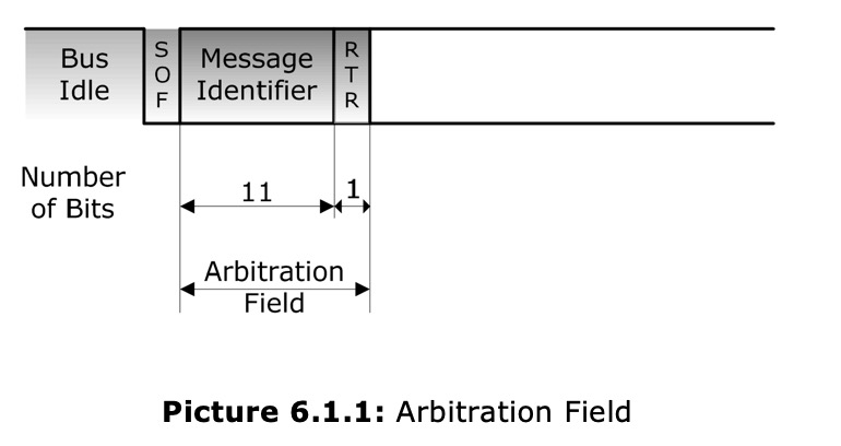
The arbitration field follows right after the SOF (Start of Frame) bit and it contains of the message ID and the RTR (Remote Transmission Request) bit.
Per definition, CAN nodes are not concerned with information about the system configuration (e.g. node address), hence CAN does not support node IDs. CAN data transmissions are distinguished by a unique message identifier (11/29 bit), which also represents the message priority. A low message ID represents a high priority.
High priority messages will gain bus access within shortest time even when the bus load is high caused by lower priority messages.
Picture 6.1.2 shows an example where three nodes in a four node CAN network try to access the bus at virtually the same time. In this example node C will win the bus access within 12 clock times. At a baud rate of 1 MBit/sec this would translate into 12 microseconds. Naturally, the bus arbitration time varies with baud rate and the message identifier length, 11 or 29 Bit.
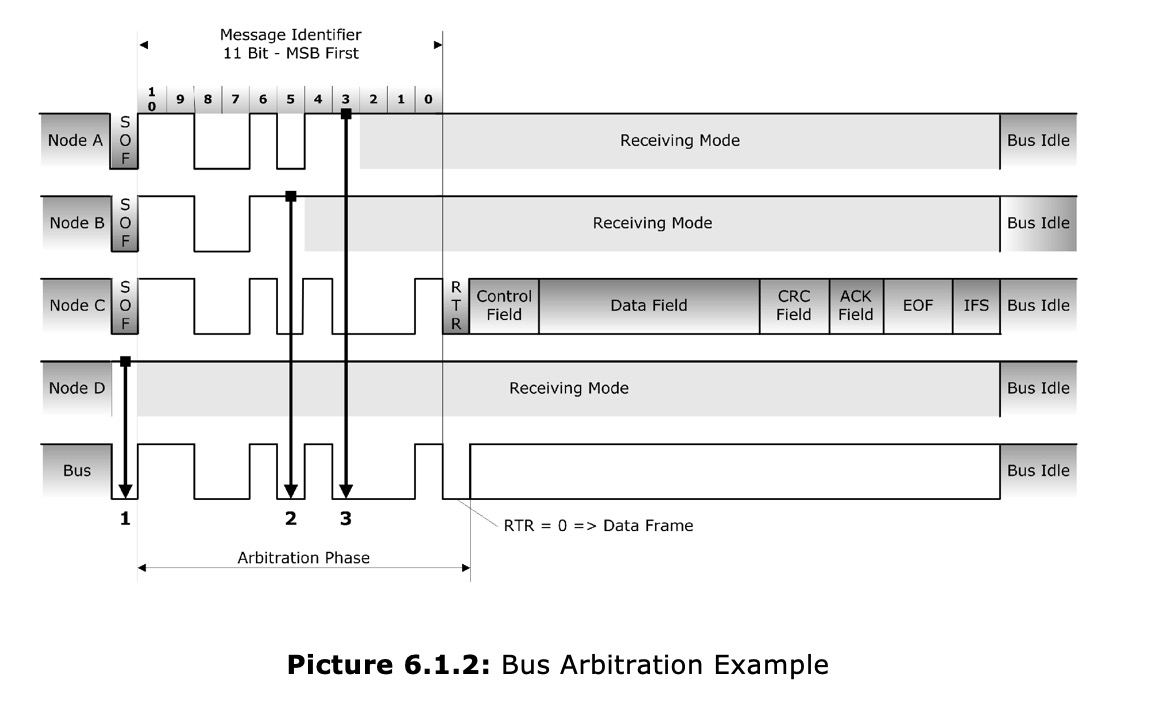
Before engaging into a detailed explanation of the arbitration process as shown in this example, it is important to lay out the ground rules on which bus arbitration works.
Main Rules of Bus Arbitration
The main rules of bus arbitration are:
- Bit wise arbitration across the Arbitration Field
Zero Bit = Dominant Bus Level, One Bit = Recessive Bus Level, dominant bit overrides recessive bit
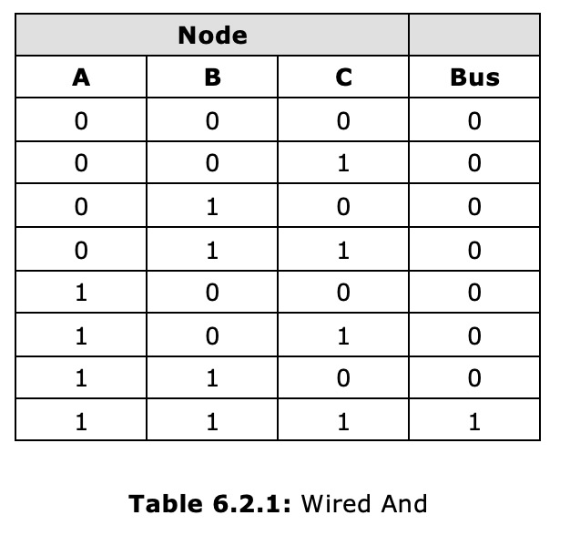
The CAN bus level will be dominant in case any number of nodes in the network output a dominant level. The CAN bus level will only be recessive when all nodes in the network output a recessive level.
An equivalent from some electronics basics will explain the relationship between node output and the resulting bus level as shown in picture 6.2.1.
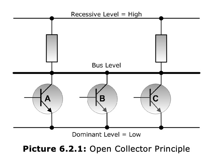
This example uses three nodes in a CAN network, in this case represented by three transistors in open-collector configuration (“Wired And”). The bus level will be at low level (dominant) in case any number of transistors in the network output a dominant level. The bus level will only be at high level (recessive) when all transistors in the network output a recessive level.
- Bus is considered idle, i.e. free for access, after end of the completely transmitted message followed by the Intermission Field.
- Node that transmits message with lowest message ID, i.e. highest priority, wins the arbitration and continues to transmit. Competing nodes switch to receiving mode (listening mode).
- Nodes that lost arbitration will start a new arbitration as soon as the bus is free for access (idle) again. Thus CAN provides a non-destructive bus arbitration.
Picture 6.2.2 demonstrates the interaction between a CAN node, trying to access the bus, and the actual CAN bus.
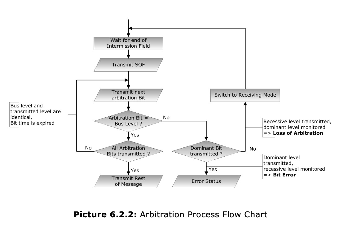
- The CAN node (CAN controller) waits for the end of the intermission field (refer to Chapter 4 - Message Frame Architecture).
- As soon as the bus is being detected as idle, the CAN node signals an SOF (Start of Frame) by putting a dominant (low) level onto the bus. Every other node in the network, that did not request bus access, will immediately switch to a receiving mode.
- The CAN controller sends the first/next message ID bit (Message IDs can be 11 or 29 bit long, the most significant bit – MSB will be sent first).
- The CAN controller compares its output signal with the actual bus level (at the end of each bit cycle).
- The node will lose the arbitration, in case it did send a recessive level (high) and detects a dominant (low) bus level. Consequently the node will switch into receiving mode.
- An error condition exists when the node detects a recessive level on the bus after it did output a dominant level. This is a clear violation of the CAN standard and the node will send an error frame to the bus.
- If the node has finished sending all arbitration bits (message ID plus RTR) without loosing the bus arbitration, it will transmit the rest of the message. At this time all other CAN nodes in the network will have switched to receiving mode.
Dual CAN Bus Interface For Arduino Due With Extended Power Range

The jCOM.CAN.DUE-X, a dual CAN bus interface for the Arduino Due, is not an Arduino shield in the common sense.
The board incorporates dual CAN transceivers required by the two integrated CAN ports on the Arduino Due while allowing the operation with any Arduino-compatible shield that supports the necessary 3.3 VDC power requirements.
By combining our dual CAN port interface, the Arduino DUE microcontroller, an OBD2 or SAE J1939 cable, and open-source software libraries you are ready to go with powerful a turn-key Arduino-based dual CAN bus solution.
Leverage the 32-bit processing capability of the Arduino DUE plus the built-in CAN ports for your next prototype.
In order to more efficiently serve automotive and industrial applications, the jCOM.CAN.DUE-X board supports an extended input power range of 7 to 36 VDC to power the entire system, i.e. including the Arduino Due itself.