Recent Posts
CAN Bus Tutorial - CAN Bus Main Characteristics
Posted by on
The following is an excerpt from A Comprehensible Controller Area Network by Wilfried Voss.
Everything that has to do with Controller Area Network (CAN) is based on maximum reliability with the maximum possible performance in mind. After all, CAN was initially designed for automobiles, definitely a very demanding environment for microprocessors, not only regarding required electrical robustness but also due to high-speed requirements for a serial communication system.
Many companies in the field of medical engineering chose CAN because they have to meet stringent safety requirements. Similar problems have been faced by manufacturers of other equipment with very high safety or reliability requirements, including robots, lifts, and transportation systems.
The CAN properties can be summarized as:
- Multi-Master priority-based bus access
- Non-destructive contention-based arbitration
- Multicast message transfer by message acceptance filtering
- Remote data request
- Configuration flexibility
- System-wide data consistency
- Error detection and error signaling
- Automatic retransmission of messages that lost arbitration
- Automatic retransmission of messages that were destroyed by errors
- The distinction between temporary errors and permanent failures of nodes
- Autonomous deactivation of defective nodes
Frames
In the language of the CAN standard, all messages are referred to as frames, such as data frames, remote frames, error frames, etc. Information sent to the CAN bus must be compliant to defined format frames of different but limited length.
Any node connected to the network may transmit a new frame as soon as the bus is idle. All nodes must simultaneously accept the consistency of a frame in a CAN network.
CAN provides four different types of message frames:
- Data Frame – Sends data
Data transfer from one sending node to one or numerous receiving nodes.
- Remote Frame – Requests data
Any node may request data from another source node. A remote frame is consequently followed by a data frame containing the requested data.
- Error Frame – Reports error condition
Any bus participant, sender or receiver, may signal an error condition at any time during a data or remote frame transmission.
- Overload Frame – Reports node overload
A node can request a delay between two data or remote frames, meaning the overload frame can only occur between data or remote frame transmissions.
Multi-Master Bus Access
In order to assure a direct communication between nodes, therefore providing maximum speed combined with maximum reliability, CAN does not restrict itself to the popular client/master network configuration. In a typical CAN network, all nodes have equal rights. Every node transmitting a data/remote frame will be the bus master during that transmission.
The actual bus access is managed through non-destructive bit-wise arbitration, which provides very effective message collision avoidance in case that multiple nodes attempt to access the bus at the same time.
A possible bus access conflict is being resolved through contention-based arbitration using the message identifier. The CAN arbitration process assures in a very timely fashion that no information will be lost. The transmitter with the frame of highest priority (lowest message ID) will gain bus access.
Frames that lost the arbitration and frames that were interrupted by error conditions will be retransmitted automatically as soon as the bus is idle again.
Message Broadcasting
In a multi-master network, nodes may transmit data at any time. Each node “listens” to the network bus and will receive every transmitted message. The CAN Controller hardware, in turn, supports message-filtering, i.e., the receiving nodes will only react to data that is relevant to them.
Messages in CAN are not confirmed because that would unnecessarily increase the bus traffic. CAN assumes that all messages are compliant with the defined standard, and if they are not, there will be a corresponding response by all nodes in the network (see also Chapter 8.1 - Error Detection). All receiving nodes check the consistency of the received frame and acknowledge the consistency. If the consistency is not acknowledged by any or all nodes in the network, the transmitter of the frame will post an error message to the bus.
If either one or more nodes are unable to decode a message, i.e., either detect an error in the transmission or are unable to read the message due to an internal malfunction, the entire bus will be notified of the error condition. Nodes that transmit faulty data or nodes that are constantly unable to receive a message correctly remove themselves from the bus (see Chapter 8.3 - Fault Confinement) and thus allow restoration of proper bus conditions.
The CAN standard also defines the request of a transmission from another node employing a remote frame. The remote frame and the requested data frame use the same message identifier. However, they are distinguished by the RTR bit (Remote Transmission Request) during the arbitration process (see also Chapter 4 - Message Frame Architecture).
Message Priority
Per definition, CAN nodes are not concerned with information about the system configuration (e.g., node address, etc.); hence CAN does not support node IDs. Instead, receivers process messages utilizing an acceptance filtering process, which decides whether the received message is relevant for the node’s application layer or not. There is no need for the receiver to know the transmitter of the information and vice versa.
CAN data transmissions are distinguished by a unique message identifier (11/29 bit), representing the message priority. A low message ID represents a high priority. A single CAN node may send or receive any number of messages, which contributes, yet again, to a maximum level of flexibility.
High priority messages will gain bus access within the shortest time even when the busload is high due to the number of lower priority messages.
Message transmissions are usually event-driven to reduce the busload, and that guarantees short latency times for real-time applications.
Short Messages
CAN supports messages between 0 and 8 bytes in length. Initially, this may seem to be a disadvantage compared to other technologies, but a short data length also assures short latency times for high priority messages.
Additionally, a limited data length contributes to the ability to withstand the strain of harsh electrical environments.
A message length of a maximum of 8 bytes is sufficient for data communications in cars, smaller machines such as household appliances, and lower level automation. Higher-Layer protocols such as CANopen support segmented transmission of data of unlimited length that are more suitable for complex automation tasks such as motion control. However, CANopen still supports the limited 8-byte messages (Process Data Objects = PDO).
These messages are usually assigned a high priority and, according to the CAN standard, they are able to interrupt the segmented transfer of low priority data (Service Data Object = SDO) after each completed data segment of 8 bytes. The low priority data transfer will resume right after the high priority message has been transmitted.
Data Rate And Message Frequency
A maximum CAN baud rate of 1 MBit/sec may not sound much. Still, the combination of very short messages, the very effective collision avoidance, error detection, and fault confinement capabilities makes CAN much more suitable for real-time applications than, for instance, TCP/IP with its up to 100 MBit/sec transmission speed. After all, CAN was designed for real-time control, while TCP/IP was designed for data transfer where exact timing is not mandatory.
The maximum number of CAN messages per second is 8,771 (at 1 MBit/sec, 8 bytes per message), up to 17,543 at 1 MBit/sec, and 1 byte per message (average bit stuffing applied, see also Chapter 7.2 - Bit Stuffing). This results in a data transfer between 17,543 and 70,168 data bytes per second (Net data transfer, without protocol overhead).
Bus Arbitration
Since a serial communication system such as CAN is based on a two-wire connection between nodes in the network, i.e., all nodes are sharing the same physical communication bus, a method of message/data collision avoidance is mandatory to assure a safe data transfer and to avoid delays resulting from the necessary restoration of proper bus conditions after the collision.
A collision may occur when two or more nodes in the network are attempting to access the bus at virtually the same time, which may result in unwelcome effects, such as bus access delays or even destruction or damage of messages.
CAN provides a non-destructive bus arbitration, i.e., no message gets lost. Higher priority messages will win the bus access, while low priority messages wait until their time has come.
Based on a 1 MBit/sec baud rate and an 11 Bit message identifier, the arbitration process is finished after 12 microseconds.
Error Detection And Fault Confinement
Rather than providing a message confirmation, which would increase the busload, CAN goes the more aggressive route of assuming that all messages must be consistent with the defined standard. Every diversion from this standard is detected and reported immediately, i.e., the error detection replaces the message confirmation. Naturally, confirmed messages would occur more often than actual error messages.
Each node in the network will receive each transmitted message. A message filter guarantees that the node knows when to ignore a message or to process it. However, each node in the network will check the transmitted message for compliance with the defined standard. All receiving nodes check the consistency of the received frame and acknowledge the consistency. If the consistency is not acknowledged by any or all nodes in the network, the transmitter of the frame will post an error frame to the bus.
The occurrence of an error frame may have two reasons. First, the transmitted data frame was, in fact, faulty or second, the data frame was correct, but one node erroneously reported an error due to a local reception problem.
It is important to distinguish between temporary errors or permanent failures of a node. CAN controllers address this problem by providing two different error counters, one for transmit errors and one for receive errors. If either counter exceeds a programmable limit, the node is considered faulty.
As part of the fault confinement, the CAN protocol allows the “removal” of a CAN node from the network if the node produces a constant stream of errors and therefore increases the busload unnecessarily.
CAN also provides very short error recovery times of a maximum of 23 bit-times. With a baud rate of 1 MBit/sec this translates into maximal 23 microseconds.
PiCAN 2 - CAN Bus Interface for Raspberry Pi
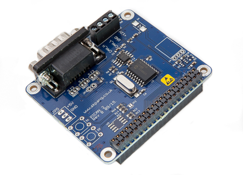
This PiCAN2 board provides Controller Area Network (CAN) Bus capabilities for the Raspberry Pi. It uses the Microchip MCP2515 CAN controller with MCP2551 CAN transceiver. Connection are made via DB9 or 3-way screw terminal.
There is an easy-to-install SocketCAN driver, and programming can be accomplished in C or Python.
The PiCAN board is fully compatible with the new Raspberry Pi 4 Model B.
 Loading... Please wait...


