Recent Posts
CAN Bus Prototyping With Arduino Uno - Simple CAN Bus Shield Test
Posted by on
This post is part of a series about Controller Area Network (CAN Bus) Prototyping With the Arduino Uno.
The most exciting part about this project is when it comes to the point where two CAN nodes communicate with each other. I started off with writing a simple program that sent messages that were received by my USB-to-CAN gateway and its Windows monitoring software. From there on, I extended the program to also receive CAN messages and display them on the Arduino serial monitor.
In a later chapter, I will also show a Windows programming example that establishes a communication with the Arduino.
The following represents a very simple CAN test program that periodically (i.e. every 1 second) sends out a CAN message with a 29-bit identifier at a baud rate of 250 kbit/sec.
// Simple CAN Shield Test
#include
"mcp_can.h"
#include <SPI.h>
MCP_CAN CAN0(10); // Set CS to pin 10
unsigned char stmp[8] = {0x30, 0x31, 0x32, 0x33, 0x34, 0x35, 0x36, 0x37};
// SYSTEM: Setup routine runs on power-up or
reset
void setup() {
// Set the serial interface baud rate
Serial.begin(9600);
// Initialize the CAN controller
// Baud rates are defined in mcp_can_dfs.h
if (CAN0.begin(CAN_250KBPS) == CAN_OK)
Serial.print("CAN Init OK.\n\r\n\r");
else
Serial.print("CAN Init Failed.\n\r");
}// end setup
// Main Loop - Arduino Entry
Point
void loop()
{
// Send data:
id = 0x1FF, extended frame, data len = 8, stmp: data buf
// ID mode (11/29 bit) defined in
mcp_can_dfs.h
CAN0.sendMsgBuf(0x1FF, CAN_EXTID, 8, stmp);
// Run in 1 sec interval
delay(1000);
}// end loop
Note: To download this sample code, see the section behind the Table of Contents.
While the code is short and sufficiently self-explanatory, let me explain the steps taken in the program.
In the setup() routine, the program initializes the serial interface (USB) to a baud rate of 9600 bps (Please make sure that your Arduino serial monitor is set to the same rate).
It then initializes the CAN controller to a data transmission rate of 250 kbits/sec and displays possible error messages on the Arduino serial monitor.
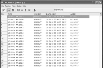
In the main loop() routine, the program sends an 8-byte CAN message using an ID of 0x1FF in extended messaging format (29-bit message ID). The actual message (unsigned char stmp[8] in this example) contains a string from ASCII 0 to 7, which can be easily spotted when using a data monitoring software.
Using my test conditions, the message was received through the USB-to-CAN gateway and displayed under Windows:

While this program may not be very useful without a CAN Bus monitoring software (meaning you can’t see the result), in the least it demonstrates how simple CAN Bus programming can be.
 Loading... Please wait...
