 Loading... Please wait...
Recent Posts
Arduino Due: Dual CAN Port Test Sketch
Posted by on
Let me, first of all, stress the point that the two CAN ports on the Arduino Due are practically useless without their respective CAN transceivers. CAN transceivers convert a regular TTL signal from the CAN controller into a differential voltage, which in turn contributes to the vast reliability of a Controller Area Network. For more detailed information on that topic, see also my post: ARM Cortex M3 Development Boards Require External CAN Bus Transceiver.
We at Copperhill provide a few options to add the transceivers to the Arduino Due, and they all work equally fine:
- CAN Bus Breakout Board 3.3 VDC
- CAN Bus Breakout Board 5 VDC
- CAN Bus Mini Breakout Board
- Dual CAN Bus Interface for Arduino Due
- Dual CAN Bus Interface for Arduino Due With Extended Power Range
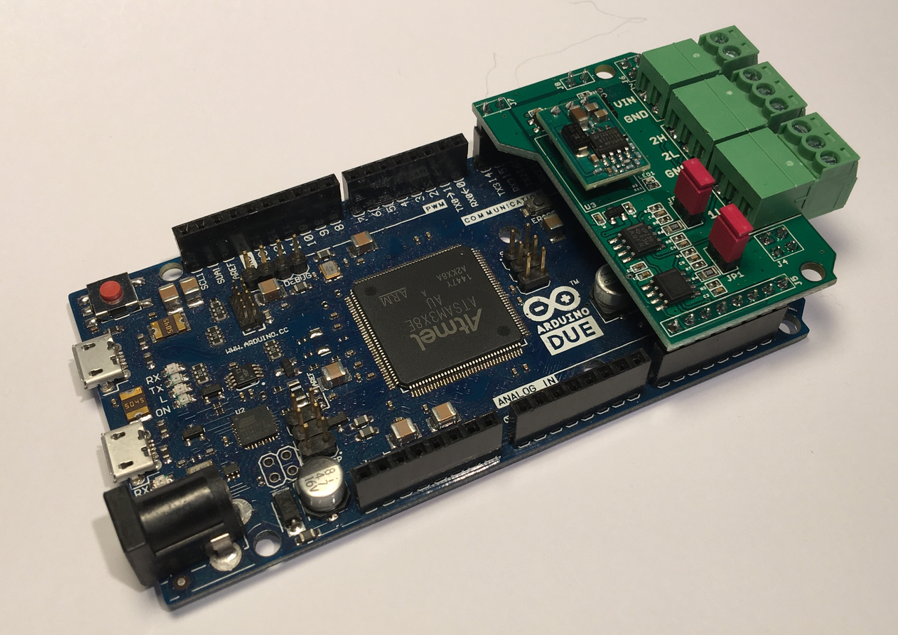
In the following, I used our Dual CAN Bus Interface for Arduino Due (as seen in above image) out of mere convenience, because the board fits directly onto the Arduino Due and does not require as much external wiring than with the breakout boards.
In order to test the Due's CAN capabilities, I simply connected both CAN ports (CAN_H, CAN_L) as shown in the above image. It may sound very obvious, but in order to test your CAN interface, you need two CAN nodes, and the Arduino Due provides that in one hardware solution.
Also, it is important to note that both nodes must be terminated by a 120 Ohm resistor, otherwise the communication will fail. In case of the Dual CAN board, the termination resistors are activated by means of jumpers.
With the hardware taken care of, let's have a brief look at the Arduino software (sketch): The Setup portion initializes the Serial Monitor and both CAN controllers (250 kBit/sec; I like sticking with J1939 parameters). In the Loop section, I send CAN data frames through both CAN ports but both at a different frequency. In a next step, I check for reception of CAN data through both ports and print the result through the Serial Monitor. Since both ports are connected with each other, you can see the received data frames as shown in the following image.
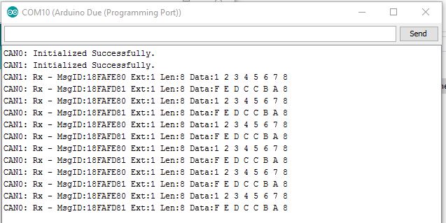
The program also tests for successful data transmission and prints a corresponding error message. You can test this by interrupting the connection between the two ports. Note, however, that the message will come with a delay, since the CAN driver software fills the internal transmission buffer before an error is detected,
The original CAN driver software is available at https://github.com/collin80/due_can, but it is also included with the Arduino Sketch I provide as a download below. I took the liberty of adding a "wrapper" around the driver functions to simplify the data initialization, data reception and transmission. However, the driver library provides enough functionality to make it worth checking it out in more detail, especially the examples in the above referenced link. I am referring here specifically to the message filtering. Out of convenience, the current setup in my Arduino Sketch admits all message IDs, while a proper message filter setup can be somewhat cumbersome.
=> Click here to download the Due_2CAN_Channel_Test Sketch (Zip file)...