Recent Posts
Arduino Due: Dual CAN Port Test Sketch With LED CAN Traffic Indicators
Posted by on
In a previous post ( Arduino Due: Dual CAN Port Test Sketch), I demonstrated how to read and write the two CAN ports on the Arduino Due.
The post explains that the two CAN ports on the Arduino Due are practically useless without their respective CAN transceivers. CAN transceivers convert a regular TTL signal from the CAN controller into a differential voltage, which in turn contributes to the vast reliability of a Controller Area Network.
We at Copperhill provide a few options to add CAN Bus transceivers to the Arduino Due, and they all work equally fine:
- CAN Bus Breakout Board 3.3 VDC
- CAN Bus Breakout Board 5 VDC
- CAN Bus Mini Breakout Board
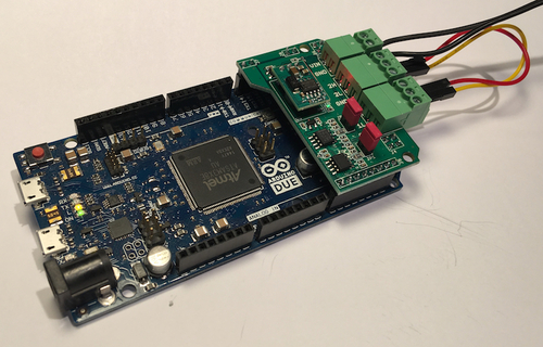
- Dual CAN Bus Interface for Arduino Due
- Dual CAN Bus Interface for Arduino Due With Extended Power Range
However, in the following, I will refer to our Dual CAN Bus Interface for Arduino Due, because it is the only board that provides control over two on-board LEDs (besides the hard-wired Power LED). We will use these LEDs to indicate CAN Bus data traffic, either receiving or transmitting data.
One obstacle, though, during the initial development of the program was the necessary use of timers, preferably driven by interrupts. The idea is to trigger the LEDs during reception or transmission for a minimum time of 5 milliseconds. The Arduino's standard delay(xx) function will not do, since it blocks the operation of the program. The use of interrupt-driven timers allows access to the CAN controllers at the highest possible processor speed.
And yes, there is support for interrupt-driven timers for the Arduino Uno and the Mega 2560. However, things are a bit different with the Arduino Due, since it uses an ARM Cortex-M2 processor. After some research, I found the solution at http://forum.arduino.cc/index.php?topic=130423.0.
The important functions are startTimer to initialize the timer frequency and define the interrupt service routine (ISR) and TC3_Handler, representing the ISR. In the ISR, I call my own timer control function, which is based on the Timer structure.
struct Timer
{
int nCount;
bool bStart;
bool bExpired;
};
Have a look at the TimerControl.cpp file (in the sketch that you can download below) to investigate the functionality of the program. The main chunk of the program is derived from the previously mentioned post (Arduino Due: Dual CAN Port Test Sketch).
The major difference, though, shows in the use of timers in the loop() section of the program. Instead of the delay() function, I first initialize timers and during operation, I check whether or not the timer has expired, at which time I trigger the corresponding action (transmitting a CAN message, controlling the LEDs).
The function LEDControl triggers the LEDs as soon as there is CAN activity. The CAN data traffic activity is set either during reception or transmission of a CAN data frame in the DueCANLayer.cpp module.
=> Download the Due_2CAN_Channel_Test_With_LEDs sketch (zip file)...
A Comprehensible Guide to Controller Area Network by Wilfried Voss represents the most thoroughly researched and most complete work on CAN available in the marketplace.
Controller Area Network (CAN) is a serial network technology that was originally designed for the automotive industry, especially for European cars, but has also become a popular bus in industrial automation as well as other applications.
The CAN bus is primarily used in embedded systems, and as its name implies, is a network technology that provides fast communication among microcontrollers up to real-time requirements, eliminating the need for the much more expensive and complex technology of a Dual-Ported RAM.
This book provides complete information on all CAN features and aspects combined with a high level of readability. Read more...
 Loading... Please wait...


