 Loading... Please wait...
Recent Posts
App Note: Testing Arduino Due With 2 CAN Bus Breakout Boards
Posted by on
 The availability of Controller Area Network (CAN) interfaces in combination with other interface technologies explains the vast popularity of the ARM Cortex-M3 processor in the CAN and SAE J1939 industry. The processor provides the means to easily and quickly create applications like CAN/J1939 gateways, CAN Bridges, J1939 ECUs, J1939 Data Logger, and many more.
The Arduino Due is the first ARM-based Arduino development board. The programming of the microcontroller is accomplished through the familiar Arduino IDE (Windows, Mac), keeping the programming as backward compatible to other Arduino systems as possible, thus allowing a smooth migration between processor systems.
Just like any other ARM M3 processor, the Due supports two CAN ports. The downside, though, is the mere fact that the Due's CAN capabilities are basically useless without additional hardware components. In order to save costs, but at the same time enabling the user to pay only for the interfaces needed for the project, the board design is limited to providing the processor with the bare necessities, while routing all interfacing signals “as is” to onboard connectors.
For instance, the serial interfaces such as Controller Area Network (CAN) and UART (RS-232/422/485) provide only TTL levels, and you will need additional hardware (transceivers) to make them hardware-compliant with their respective standards. For more detailed information, see my post ARM Cortex M3 Development Boards Require External CAN Bus Transceiver.
There are several options to add the necessary CAN transceivers to the Due board:
- Arduino DUE CANShield With 2 CAN Ports
- CAN Bus Breakout Board 3.3 VDC
- CAN Bus Breakout Board 5 VDC
- CAN Bus Mini Breakout Board
In the following , I will describe a test of the Arduino's CAN Bus capabilities using our CAN Bus Mini Breakout Board.
For further detailed information about the software driver and the software download, please refer to my post App Note: Arduino Due 2-Channel CAN Bus Driver Software.
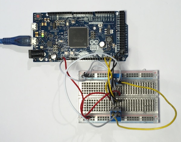
The picture above shows the test configuration I used, which includes the Arduino Due, two CAN Bus breakout boards, and a bread board to connect all components. Both lines of the CAN Bus breakout boards, CAN_H and CAN_L are connected with each other.
This configuration allows a first, very simple test of the Arduino Due's CAN Bus capabilities by creating an application that sends CAN data through one channel and receive it through the other (and vice versa).
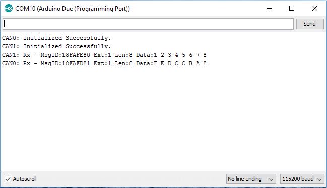
To take the result upfront, have a look at the picture above. It shows the successful initialization of both CAN channels plus the first two received CAN Bus data frames for each CAN Bus channel.
On a side note: For a very first test, I skipped installing the CAN Bus breakout boards, and connect the TTL-Level signals CANRX, CANTX instead, however, with no success. The CAN controller initialization went without problems, but neither controller was able to send a data frame. I am not a hardware specialist, so I let it be and used the breakout boards, in this case without further problems.
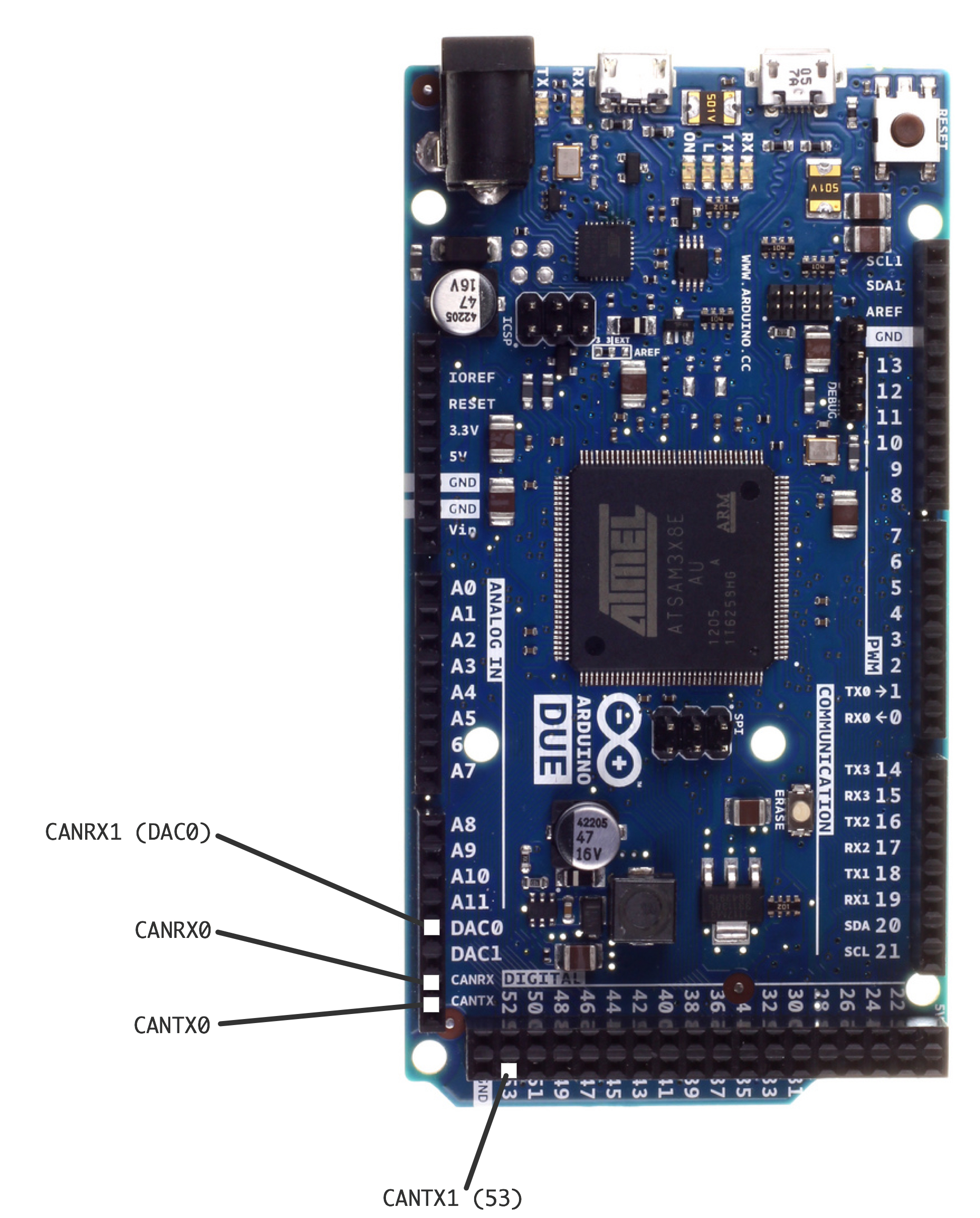
Now, let's have a look at the hardware installation, first of all, the signals coming from the Arduino Due:
Each of the CAN Bus breakout boards, naturally, requires a power supply, which is provided through the Due board as well (have a look at the corresponding pins on the upper left portion of the board). Available voltages are either 3.3VDC or 5VDC.
For the CAN Bus Mini Breakout board, I needed the 3.3 VDC power (we have further breakout boards that run with 5VDC; see list above in this post).
The lower left corner of the board contains the CAN bus connections for both controllers; this is the extended section compare to, for instance, the Arduino Uno.
Important know!
Both CAN Bus breakout boards provide their corresponding CANRX and CANTX lines, but, defying an engineer's instinct, you don't cross the lines to connect receiver to transmitter (as you would do, for instance, with RS232).
The connections are as follows:
- CANRX0 -> CANRX CAN Bus Breakout Board #1
- CANTX0 -> CANTX CAN Bus Breakout Board #1
- CANRX1 -> CANRX CAN Bus Breakout Board #2
- CANTX1 -> CANTX CAN Bus Breakout Board #2
The above connection list does not include the power supply, which I deemed obvious.
Note: If you prefer to skip the installation with bread board and prototyping wires but would prefer an off-the-shelf solution, have a look at our Arduino Due CAN Shield with 2 CAN Ports. The test software we created will work for all variants of CAN Bus transceivers.
Download the Arduino Due Sketch
As I mentioned before, the Arduino Due test program (sketch) was designed to send out CAN data frames through one channel and received it through the other (and vice versa).
Disclaimer: All Arduino sketches and other code samples and projects as introduced here are free software; you can redistribute and/or modify them. The programs are introduced in the hope that they will be useful, but WITHOUT ANY WARRANTY; without even the implied warranty of MERCHANTABILITY or FITNESS FOR A PARTICULAR PURPOSE. With downloading these programs, you confirm that these code samples and projects were created for demonstration and educational purpose only.
=> Download the Due_2CAN_Channel_Test Sketch for Arduino Due (zip file)...
Last, but not least, a few tips...
- Make sure you have the latest Arduino IDE installed (check at arduino.cc). The Arduino people have this absolutely annoying habit of providing updates that are far from backwards-compatibility, meaning compiling a perfectly good program may result in an enormous list of inexplicable error messages.
- Make sure, your IDE is set up for the Arduino Due. Go to Tools->Boards->Boards Manager to install Due capabilities.
Programming Arduino Getting Started with Sketches
by Simon Monk
 Clear, easy-to-follow examples show you how to program Arduino with ease! "Programming Arduino: Getting Started with Sketches" helps you understand the software side of Arduino and explains how to write well-crafted Sketches (the name given to Arduino programs) using the C language of Arduino. This practical guide offers an unintimidating, concise approach for non-programmers that will get you up and running right away.
Programming Arduino: Getting Started with Sketches explains basic concepts and syntax of C with simple language and clear examples designed for absolute beginners - no prior knowledge of programming is required. It leads you from basic through to advanced C programming concepts and features dozens of specific examples that illustrate concepts and can be used as-is or modified to suit your purposes.
- All code from the book is available for download.
- Helps you develop working Sketches quickly.
Coverage includes: C Language Basics; Functions; Arrays, Strings; Input / Output; Standard Library Goodies; Storage; LCD Displays; Programming for the Web; Program Design; C++ and Library Writing