 Loading... Please wait...
Recent Posts
CANFDuino: Upgrading the Hardware to 24 VDC Power Supply
Posted by on
Today, we are addressing a frequently asked question since the product's launch: 'Is it possible to power CANFDuino off of 12 or 24 V power?'. Our previous response, 'Yes, using the prototyping space to add a regulator', while accurate, may not have been as helpful as we intended. To provide a more practical solution, we have prepared a straightforward, step-by-step guide that will walk you through the modification needed to power the CANFDuino off of 12-24 V without relying on the USB connection as the primary power source.
A voltage regulator, a key component in our CANFDuino modification, is a device that maintains a constant voltage level. It does this by adjusting the current flow in the circuit in response to changes in voltage, and in simple terms, can be thought of as a 'voltage converter.' Voltage regulators can be either linear or switching devices, where switching devices are typically more efficient but may require more components, and linear devices are simpler but less efficient, as they require efficient heat dissipation when running under heavy load.

To simplify things, we will utilize a linear regulator to convert our 12-24 V input into a steady 5 V power source for our CANFDuino. We have chosen the LM7805 regulator for this task due to its long-standing reliability, affordability, and availability in various packaging options.
Note: The following modification worked for us based on our specific parts and setup. Your setup may differ, so there is a risk of failure, including potentially damaging the processor, when making any modifications.
Step 1: Design Circuit
The LM7805 regulator typically requires only 1-2 additional components. These are usually input and output capacitors, stabilizing the incoming voltage and reducing any high-frequency interference that could affect the semiconductors relying on the 5V power supply.
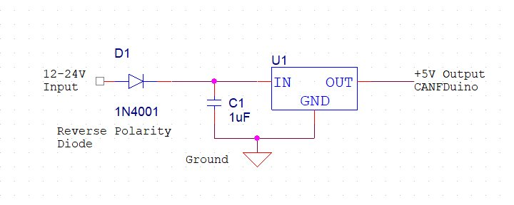
The diagram above displays the circuit to be integrated into the CANFDuino. It includes a regulator, an input capacitor, and a blocking diode. The blocking diode is crucial as it safeguards the board from damage caused by reverse polarity. It prevents any harm from occurring if the black and red wires are unintentionally switched. We have all made this mistake at some point, so it's valuable information to include. We have decided not to include an output capacitor since the CANFDuino already has one on the 5V input side of the built-in 3.3V regulator.
Step 2: Buy & Build
Let's begin with a simple step: Visit Mouser and select the components that suit your needs and comfortably fit into your prototyping space. The CANFDuino supports SMT and through-hole components, so we used a combination of both for this circuit, as these components were available.
When soldering parts onto the CANFDuino, it's important to be careful. Do not solder the regulator output to the 5 V area of the CANFDuino until you have built and tested the circuit. It's best to build and test the circuit separately from the rest of the CANFDuino to avoid any damage. Once the circuit works properly, you can connect to the CANFDuino’s 5 V area. This is recommended for all modifications.
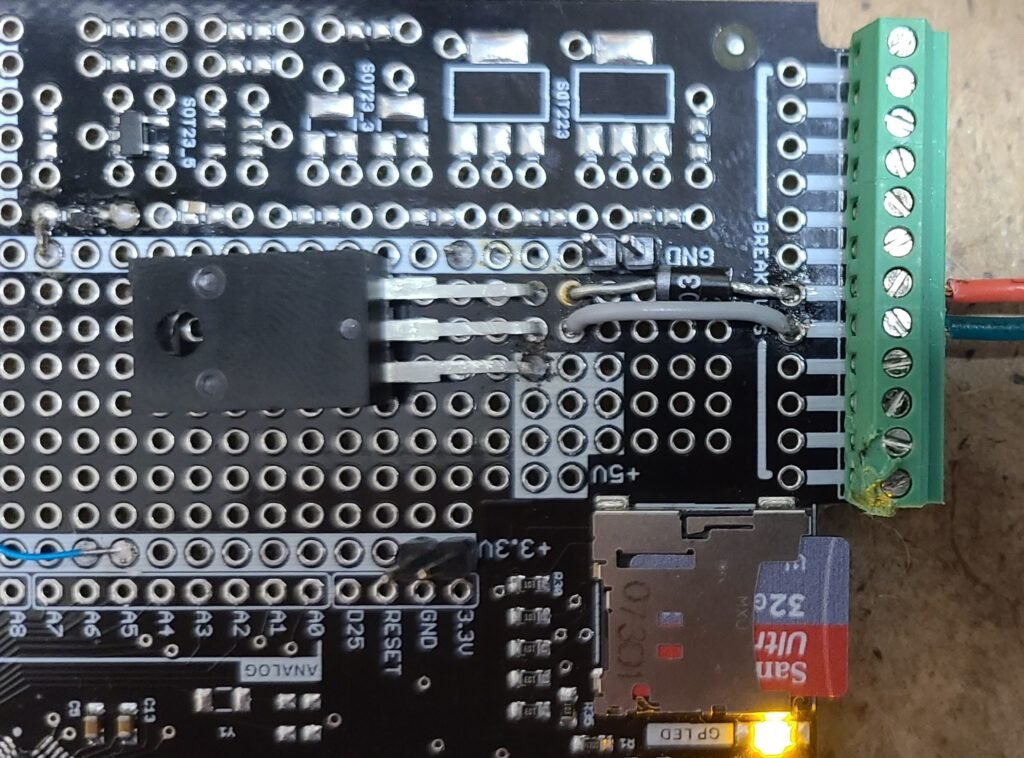
The image above shows our fully assembled mod after testing and connecting to a 5V power source. In the photo, we use breakout connections to the terminal blocks for easier wiring to our 12-24V input (red for positive input, green for negative input). Additionally, you'll notice a small capacitor on the SMT pads with wires running underneath. We've also flipped the regulator for easier mounting and soldering, which changes the orientation of the input and output pins from the diagram.
Step 3: Test Circuit
After soldering all components in place and making the power connections to the terminal block, it’s time to test. Here's how: Connect your 12-24 V source to the terminal block wiring. Then, using a DMM, check the output terminal pin; it should read 5 V. If you have good output from the regulator, power down the circuit and solder it to the 5 V area. If you do not measure 5 V, review your circuit design, regulator pinout, and components, and check the integrity of your solder connections. Once corrected, try the test again until you succeed.
Step 4: Wire and Power On
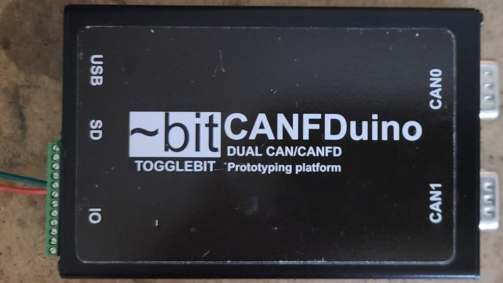
After soldering the regulator output to the 5V section, remove the boot jumper (if installed) and switch on the 12-24V power. You should notice the orange GPLED blinking, indicating the bootloader is entered. Now, you can power your CANFDuino permanently from the 12V input and connect USB whenever necessary to program the unit or monitor bus traffic. Additionally, you can combine this modification with our Bluetooth upgrade to keep the CANFDuino connected to a vehicle and establish a wireless connection.
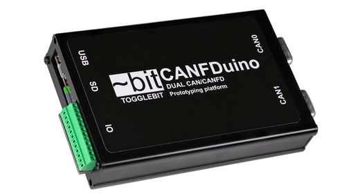
CANFDuino - Dual CAN/CANFD Prototyping Platform
The CANFDuino is a fully-equipped embedded system designed for real-world applications. It integrates essential features such as dual CAN/CANFD ports, an SD card slot, and numerous analog and digital I/O. In addition, it includes an onboard prototyping shield for SMT and through-hole components, a sturdy aluminum enclosure, and durable connectors.
The CANFDuino supports CANFD, the latest version of the CAN Bus standard, which accommodates speeds of up to 5 Mbps. It has two native ports with DB9 connectors in an enclosure, ready to be mounted on your vehicle or installed in your autonomous project. This platform suits tinkerers, hackers, and industry professionals seeking an off-the-shelf, open-source CAN Bus solution that requires minimal or no hardware assembly.