 Loading... Please wait...
Recent Posts
The Benefits Of Controller Area Network - CAN Bus - For Embedded Applications
Posted by on
The following is an excerpt from A Comprehensible Controller Area Network by Wilfried Voss.

Controller Area Network, like any field-bus system based on serial communication, will reduce wiring, which was initially considered only as an advantageous side effect.
Distributed control, i.e., the use of a multi-processor system, will consequently result in increased performance, and the vastly reduced costs of microcontroller chips in the market made the use of multiple processors in one embedded system affordable.
Other advantages include increased reliability and improved service and maintenance features.
Another significant benefit of applying the CAN technology is apparent during the time-consuming and costly hardware and software development process.
Both, the Physical Layer and the Data Link Layer, as defined in the ISO 11898 standard, are already implemented in silicon, either in the form of a stand-alone CAN controller or integrated into multi-function single-chip microcontrollers.
CAN Controller Firmware
As demonstrated in the picture below, the ISO/OSI Reference Model specifies seven levels beginning with the physical connection up to the actual user application, i.e., the Application Layer.
The standard CAN Bus implementation bypasses the connection between the Data Link Layer and the Application Layer to save on valuable memory resources by minimizing the overhead and, as a result, gaining performance as needed for embedded solutions with limited resources.
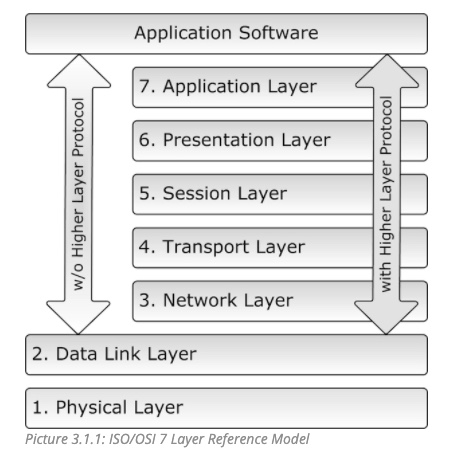
Layers 3 through 6, i.e., all layers above the Data Link Layer, require additional software resources, which are provided by higher layer protocols such as CANopen, DeviceNet, and SAE J1939.
The Application Layer is the layer that interacts with the operating system or application of the CAN device.
The Data Link Layer connects the actual data to the protocol in terms of sending, receiving, and validating data. Under CAN, it represents the data exchange, including error detection/recovery and fault confinement, transmission acknowledgments, etc., and all the ingenious CAN Bus features.
The Physical Layer represents the actual hardware, i.e., the physical connection between nodes in a network and the electrical signal characteristics such as voltage levels and timing.
The software development engineer will benefit from the fact that under CAN, the two lowest layers, the Physical Layer and Data Link Layer, are already integrated into silicon. That reduces the software development process by concentrating solely on the coding of the actual application software.
Most semiconductor manufacturers and vendors in the CAN Bus business, provide source code (e.g., for LINUX) and libraries (e.g., Windows APIs) for all function calls that represent the connection between the Data Link Layer and the Application Layer.
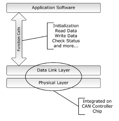
The nature of the necessary function calls is identical to those needed for the access of any hardware device (drivers):
- Initialization
- Read Data
- Write Date
- Check Status
Naturally, this is just an elementary list of function calls. Most code libraries provide extended functionality like the determination of the busload, and more.
Low-Cost Implementation
Most major semiconductor manufacturers, including Motorola, Philips, Intel, Infineon, among others, sell CAN Bus chips, and the fact that millions of them are used in automobiles guarantees low chip prices.
Implementing the CAN Bus technology into a new application can be accomplished with lower hardware costs and less development time than, for instance, RS232/485 or TCP/IP.
CAN Bus software libraries, including CANopen or DeviceNet protocol stacks, require a significantly lower memory footprint and far less CPU performance than any TCP/IP implementation.
Speed, Reliability, And Error-Resistance
Controller Area Network provides the ability to function in challenging electrical environments, a high degree of real-time capability, and ease of use. The real-time capabilities are supported by extremely short arbitration times in the range of microseconds, limited data length, and extremely short error recovery times, again, in the range of microseconds.
The reliability and error resistance of CAN has been calculated in a mathematical model. Here is an example using the following parameters and conditions:
- 1 Bit error every 0.7 sec
- Baud rate of 500 kBit/sec
- Operation of 8 hours/day and 365 days/year
According to the mathematical model, the Residual Error Probability will be 1 undetected error in 1000 years.
Worldwide Acceptance
The CAN Bus technology is supported by many suppliers and manufacturers all over the world who provide CAN controllers, CAN interface boards, CAN analyzing software tools, and higher-layer protocols.
As I mentioned previously, many major semiconductor manufacturers, including Motorola, Philips, Intel, Infineon, and many others, sell CAN chips, and the fact that millions of them are used in automobiles guarantees low chip prices and long-term availability.
The use of CAN in most of European passenger cars and the decision by truck and off-road vehicle manufacturers for the CAN Bus led to the availability of CAN chips since 1987.
Other high volume markets, like domestic appliances and industrial control, also increase the CAN sales figures and guarantee the availability for the future.

Arduino-Due-Based ECU Development Board With Two CAN Bus Ports
The CAN Bus board incorporates dual CAN transceivers required by the two integrated CAN ports on the Arduino Due, i.e. they convert the CAN TTL signal into a differential voltage as required by the CAN Bus Standard (ISO 11898).
The board is fully compatible with the open-source Arduino Software (IDE), making it easy to write C code and upload it to the board. It runs on Windows, Mac OS X, and Linux.
The Due Core is a microcontroller board based on Arduino Due, featuring the Atmel SAM3X8E ARM Cortex-M3 CPU.
The Due Core is a compact version of the Arduino DUE. It integrates all peripherals required for the MCU, and all GPIO are connected to 2.54mm connectors.