 Loading... Please wait...

Blog
Recent Posts
CAN FD and SAE J2716 SENT: Automotive Sensor Communication, Testing, and Applications
Posted by on
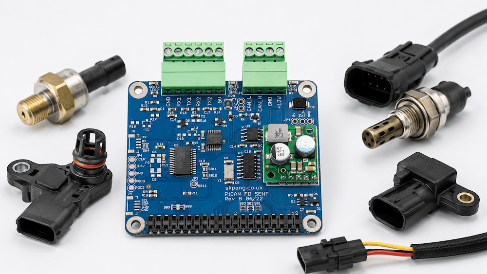 Modern automotive and industrial control systems rely on several communication technologies, each optimized for different tasks. CAN and CAN FD are widely used for communication between electronic control units, while sensor interfaces such as SAE J2716 SENT provide an efficient way of transferring high-resolution measurements from sensors to those controllers.
Combining CAN FD and SENT on the same development platform can therefore provide a useful bridge between the sensor level and the vehicle network level.
A Brief Introduction to CAN FD
CAN FD (CAN with Flexible Data-Rate) is an extension of the Classical CAN protocol. It maintains the fundamental arbitration and reliability mechanisms that made CAN successful while addressing two important limitations of Classical CAN: payload size and data throughput.
A Classical CAN data frame carries a maximum of 8 data bytes. CAN FD increases the maximum payload to 64 bytes per frame.
CAN FD can also switch to a higher bit rate during the data portion of a message. Arbitration can continue at the conventional CAN bit rate, while the data phase operates at a substantially higher rate. This allows more information to be transferred without abandoning the established CAN network architecture.
CAN FD is therefore well suited to applications involving larger data sets, higher update rates, diagnostics, firmware transfers, and increasingly sophisticated electronic systems.
However, CAN FD remains primarily a network communication technology. Sensors themselves do not necessarily need the complexity or cost of a complete CAN interface. This is where protocols such as SAE J2716 SENT become useful.
What Is SAE J2716 SENT?
SENT stands for Single Edge Nibble Transmission and is standardized by SAE International under SAE J2716.
SENT was developed specifically for transmitting sensor information to electronic control units. Unlike CAN, which is a multi-node network protocol, SENT is fundamentally a point-to-point sensor communication interface.
A typical arrangement is straightforward:
Sensor → SENT → ECU
The sensor continuously provides measurements to the controller over a dedicated signal connection.
SENT is a unidirectional protocol. Its primary purpose is not general-purpose communication between intelligent devices but the reliable transmission of sensor values from a sensor to the controller that needs those measurements. SAE describes SENT as a point-to-point scheme intended to provide high-resolution sensor data while maintaining relatively low system cost.
This makes SENT particularly attractive as a digital alternative to traditional analog sensor outputs.
How SENT Transmits Data
One interesting aspect of SENT is that it does not use a conventional serial data stream with a separate clock.
Instead, information is encoded in the time interval between signal edges. The receiving controller measures these intervals and converts them into digital values.
The fundamental data unit is a nibble, which contains four bits. Consequently, each nibble can represent a hexadecimal value from 0 through F.
A SENT message consists of a defined sequence of pulses. The frame includes synchronization information followed by status and data information and error-detection information. The synchronization portion allows the receiver to determine the timing used by the transmitting sensor.
The protocol therefore does not require the transmitter and receiver to share a separate clock signal.
A SENT implementation can also provide CRC error detection, allowing the receiving controller to identify corrupted sensor messages. Modern microcontrollers with dedicated SENT peripherals can perform functions such as data-rate synchronization, CRC checking, frame-error detection, and data buffering directly in hardware.
Why Use SENT Instead of an Analog Sensor Signal?
Many automotive sensors traditionally provide an analog voltage proportional to the measured quantity. A pressure sensor, for example, might produce a voltage that varies with pressure.
That approach is simple, but the ECU must convert the analog signal into a digital value. Accuracy can be affected by voltage references, electrical noise, wiring resistance, ADC resolution, and component tolerances.
SENT allows the sensor itself to provide a digital measurement.
This has several advantages. High-resolution sensor information can be transmitted without requiring an analog-to-digital conversion at the receiving ECU, and additional information can be included alongside the primary measurement. Error detection can also be incorporated into the communication.
At the same time, SENT remains considerably simpler than implementing a complete CAN interface inside every sensor.
SENT and CAN FD Serve Different Levels of the System
The relationship between SENT and CAN FD becomes particularly interesting when looking at the complete signal path through a vehicle or machine.
Consider a sensor measuring pressure, temperature, position, or another physical quantity.
The communication path might look like this:
Sensor → SENT → ECU → CAN FD → Other ECUs
SENT handles the short, dedicated connection between the sensor and its controller.
CAN FD handles communication between controllers and other devices throughout the vehicle or machine.
The two technologies therefore complement rather than compete with each other.
A controller can acquire precise sensor measurements through SENT, process or scale those values, and then distribute the resulting information across the CAN FD network.
The reverse situation is also useful during development. A test system can receive information from CAN FD and use it to generate simulated SENT sensor signals for an ECU under test.
Why Combine CAN FD and SENT on One Platform?
For development, testing, simulation, and research, having both interfaces available on the same computer can simplify a number of tasks.
A Raspberry Pi equipped with both CAN FD and SENT interfaces can interact simultaneously with the vehicle network and with individual sensor interfaces.
This makes it possible to build relatively compact test systems capable of operating at two different communication levels.
For instance, an application could receive SENT data from a physical sensor, interpret the measurement, and transmit corresponding information over CAN FD. Conversely, software could receive CAN FD information and generate SENT output to emulate a sensor.
Such a system can be particularly useful for gateway development, ECU testing, sensor evaluation, data acquisition, and hardware-in-the-loop experiments.
Application Examples
Some practical applications for a combined CAN FD and SENT development system include:
-
Sensor evaluation — Connect a SENT-compatible automotive sensor and capture its output while simultaneously recording CAN or CAN FD network traffic.
-
ECU development — Develop an ECU that receives measurements from SENT sensors and distributes processed values over CAN FD.
-
Sensor simulation — Generate SENT messages to emulate a sensor during ECU development without requiring the actual sensor or physical process.
-
Gateway development — Convert SENT sensor information into CAN or CAN FD messages for distribution across a larger system.
-
Automotive test benches — Build a Raspberry Pi-based bench capable of interacting with both individual sensor interfaces and an ECU network.
-
Data logging — Record SENT sensor values together with CAN FD traffic to correlate physical measurements with network activity.
-
Fault testing — Generate controlled SENT data and observe how an ECU responds to changing or abnormal sensor information.
-
Prototype vehicle systems — Integrate SENT sensors into experimental CAN FD networks without developing dedicated test hardware for each interface.
-
Educational and research systems — Demonstrate the distinction between point-to-point sensor communication and vehicle-level network communication using a single computing platform.
PiCAN FD with SAE J2716 SENT
 The PiCAN FD with SAE J2716 SENT with SMPS combines these capabilities on a Raspberry Pi HAT.
The CAN interface is based on the Microchip MCP2518FD controller and supports Classical CAN as well as CAN FD. The CAN FD arbitration rate supports up to 1 Mbit/s, while the data phase supports rates up to 8 Mbit/s. Under Linux, the CAN interface appears as can0 through SocketCAN.
The SENT portion is handled by a Microchip dsPIC33 microcontroller and provides two independent SAE J2716 SENT channels. Each channel can be configured for transmission or reception, with configurable tick and frame timing. Communication between the SENT controller and Raspberry Pi takes place through UART using ASCII commands.
A 5 V output is also available for powering a small sensor, making it possible to connect and experiment with SENT devices directly.
The board additionally incorporates a 3 A switched-mode power supply (SMPS) capable of powering both the interface and Raspberry Pi from an external 7 to 24 VDC supply. This can be particularly convenient for automotive and test-bench environments where a standard Raspberry Pi USB power supply may not be desirable.
Python programming is supported, and a Python 3 demonstration GUI is available for working with the SENT interface.
From Sensor Signal to Vehicle Network
CAN FD and SAE J2716 SENT address two distinctly different communication requirements.
SENT provides a relatively simple and efficient method for transferring high-resolution digital information from a sensor to a controller. CAN FD provides the network infrastructure for exchanging larger amounts of information among controllers and other intelligent devices.
Combining both interfaces on a Raspberry Pi creates a flexible platform that can operate across these two layers.
For engineers working with automotive sensors, ECUs, gateways, test benches, or vehicle networks, this makes it possible to follow—and manipulate—the complete data path from the individual sensor signal to the CAN FD network using a single development system.
Building a Classical CAN to CAN FD Gateway with the ESP32-S3
As CAN FD continues to replace Classical CAN in automotive, industrial, agricultural, and heavy equipment applications, many engineers face a familiar dilemma: they have one or more perfectly functional Classical CAN devices that cannot simply be connected to a CAN FD network. The obvious solution would be to redesign the existing hardware and rewrite the firmware [...]
CAN Bus vs. CAN FD: When Is It Worth Upgrading? A Practical Guide for Embedded System Developers
For more than three decades, Classical CAN (Controller Area Network) has been the workhorse of industrial automation, automotive electronics, agricultural machinery, marine systems, and countless embedded applications. It has earned a reputation for exceptional reliability, deterministic communication, and outstanding error detection. Yet the demands placed on embedded networks continue to grow. Today's systems generate far more [...]
How to Build a CAN Bus Prototype Before Designing Your PCB
Modern embedded systems rarely begin with a custom PCB. In fact, the fastest and often the most successful development projects start on inexpensive development hardware that allows engineers to validate concepts, write firmware, and test communication long before the first schematic is finalized. When developing CAN Bus and SAE J1939 applications, I have found that the [...]
Raspberry Pi CAN Bus and LIN Bus Interface: CAN FD Development Made Easy
The Raspberry Pi has evolved far beyond its educational roots. With modern multi-core processors, generous memory, Linux support, and an enormous software ecosystem, it has become one of the most capable embedded computing platforms available today. When combined with a CAN and LIN interface, the Raspberry Pi transforms into an excellent development platform for automotive, industrial [...]
Building a Classical CAN to CAN FD Gateway with ESP32-S3: A Powerful Migration Platform for Next-Generation Networks
As CAN FD (Flexible Data-Rate) continues to gain adoption across automotive, industrial, agricultural, and heavy-duty vehicle applications, many developers face a common challenge: How do you connect legacy Classical CAN networks with newer CAN FD systems? One practical solution is a protocol gateway that can receive messages on one network, process or translate them, and transmit [...]
Why CAN Bus Is One of the Most Reliable Communication Systems Ever Created
When engineers design communication systems for vehicles, industrial machinery, agricultural equipment, marine electronics, and embedded control systems, reliability is often more important than raw speed. A lost message in a music streaming application may go unnoticed. A lost message containing engine speed, brake status, steering angle, or hydraulic pressure can lead to equipment malfunction, downtime, or [...]
LIN Bus Development Made Easy: Integrating Automotive LIN Networks with Any UART-Based Embedded System
Modern automobiles contain dozens of electronic control units (ECUs) that communicate with each other to manage everything from engine performance to seat adjustments. While high-speed networks such as CAN Bus handle critical vehicle functions, many automotive subsystems rely on a simpler and less expensive communication technology: the Local Interconnect Network, better known as LIN Bus. For [...]
Mastering CAN Bus: Essential Guide to Understanding and Troubleshooting Vehicle Networks
In today’s world of connected vehicles and industrial automation, understanding the details of networked communication protocols has become a pivotal skill for engineers and technicians alike. The book Mastering CAN Scratch: Understanding & Troubleshooting (ISBN/ASIN B0G24Z25RZ) steps into this space by offering a comprehensive, hands-on guide to the widely used Controller Area Network (CAN) bus [...]
Understanding the Role of LIN Bus in Automotive Networking
The Local Interconnect Network (LIN) bus is a serial communication protocol designed to facilitate cost-effective networking of sensors, actuators, and other components within automotive systems. Developed in the late 1990s by a consortium of European automakers, including BMW, Volkswagen Group, Audi, Volvo Cars, and Mercedes-Benz, along with technology partners such as Volcano Automotive Group and [...]