Blog
Recent Posts
CAN Bus Troubleshooting: A Technical Guide
Posted by on
 The Controller Area Network (CAN Bus) is one of the most robust and widely used communication protocols in automotive, industrial, and embedded systems. Its reliability and fault tolerance make it indispensable—but like any communication network, issues can arise. Troubleshooting CAN Bus problems requires a methodical approach that considers both the physical layer and the protocol layer. This guide outlines common failure modes, what to look for, and how to solve problems efficiently.
1. Understanding the CAN Bus Architecture
Before troubleshooting, it’s important to recall the structure of a CAN network:
-
Nodes (ECUs or controllers): Devices that transmit and receive messages.
-
Bus Lines: Two-wire differential signaling: CAN_H (high) and CAN_L (low).
-
Termination Resistors: Typically 120 Ω resistors at each end of the bus.
-
Topology: Linear bus with short stubs, not a star configuration.
Any deviation from these design principles can result in communication failures.
2. Common Symptoms of CAN Bus Issues
When something isn’t working, the symptoms often fall into recognizable categories:
-
No communication at all – Network appears “dead.”
-
Intermittent communication – Messages are dropped or nodes reset sporadically.
-
Error frames – The bus is congested with retransmissions.
-
Bus-off state – A node isolates itself after too many errors.
-
Dominant stuck bus – One line permanently holds a dominant state, preventing traffic.
-
High latency or jitter – Timing irregularities due to collisions or wiring faults.
3. Physical Layer Troubleshooting
a. Wiring and Termination
-
Check the twisted pair: Ensure CAN_H and CAN_L are twisted together along the entire length for noise immunity.
-
Termination resistance: Measure resistance across CAN_H and CAN_L with the system powered off. The expected value is ~60 Ω (two parallel 120 Ω resistors).
-
If you measure ~120 Ω, one termination is missing.
-
If you measure ~40 Ω or less, there may be an extra termination.
-
-
Stub length: Stubs should be as short as possible (<30 cm for high-speed CAN at 500 kbps). Long stubs introduce reflections.
b. Voltage Levels
-
With power on but idle bus:
-
CAN_H ≈ 2.5 V
-
CAN_L ≈ 2.5 V
-
-
During dominant state:
-
CAN_H ≈ 3.5 V
-
CAN_L ≈ 1.5 V
-
-
Deviations can indicate wiring swaps, short circuits, or transceiver faults.
c. Oscilloscope Checks
A scope is essential for diagnosing noise, reflections, or poor edge transitions:
-
Look for clean differential signals (roughly 2 V differential swing).
-
Detect reflections from improper terminations.
-
Check for excessive ringing caused by poor cable quality.
4. Protocol Layer Troubleshooting
a. Bit Rate Mismatch
-
Ensure all nodes are configured for the same baud rate (e.g., 125 kbps, 500 kbps, or 1 Mbps).
-
A single misconfigured node will disrupt the entire bus.
b. Identifier Conflicts
-
If two nodes use the same CAN identifier, they will “fight” for bus access.
-
This results in constant arbitration and error frames. Review the identifier map carefully.
c. Error Counters and Bus-Off State
-
CAN controllers maintain Transmit Error Counter (TEC) and Receive Error Counter (REC).
-
If TEC > 255, the node goes bus-off and stops transmitting.
-
Investigate wiring or protocol misconfigurations if repeated bus-off states occur.
d. Bus Load
-
A saturated bus (>70–80% utilization) can cause missed deadlines.
-
Measure bus load with a CAN analyzer. Reduce load by lowering message frequency or optimizing data payloads.
5. Tools for CAN Bus Troubleshooting
-
Multimeter: Quick resistance and voltage checks.
-
Oscilloscope: Signal integrity and noise analysis.
-
CAN Analyzer/Interface (e.g., PCAN, Kvaser, or ValueCAN): Captures messages, error frames, and bus statistics.
-
Protocol Decoders (e.g., Wireshark with SocketCAN): Helps identify protocol-level errors.
-
Diagnostic Software (e.g., Vector CANalyzer, BusMaster): Provides advanced analysis, error monitoring, and replay.
6. Systematic Troubleshooting Checklist
-
Check power supply to all nodes (voltage and ground integrity).
-
Verify bus termination (measure 60 Ω across the lines).
-
Inspect wiring (twisting, shorts, reversed wires, stubs).
-
Measure idle voltages (CAN_H/L around 2.5 V).
-
Scope the signals (check for reflections, ringing, noise).
-
Confirm baud rate consistency across all nodes.
-
Monitor with analyzer (look for error frames, message loss).
-
Check for overload (measure bus utilization).
-
Isolate faulty nodes by removing devices one by one until the bus stabilizes.
-
Reintroduce nodes methodically while monitoring the bus.
7. Preventative Measures
-
Use proper shielded twisted-pair cabling in noisy environments.
-
Always design with correct termination and topology.
-
Apply galvanic isolation for nodes in harsh or high-voltage systems.
-
Keep software updated to avoid identifier conflicts.
-
Monitor bus health during development with an analyzer to catch issues early.
Conclusion
Troubleshooting CAN Bus problems requires a layered approach: start with the physical layer, then move up to protocol diagnostics. Most issues stem from improper wiring, missing terminations, or misconfigured bit rates. With the right tools and methodology, even the most elusive CAN network issues can be identified and resolved quickly.
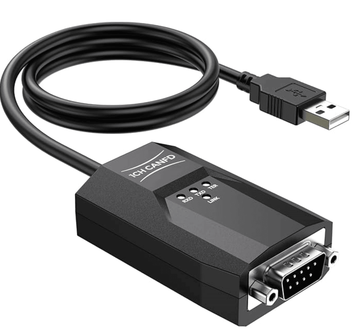
 USB to CAN Analyzer Cable SavvyCAN-FD- C
High-Speed USB to CAN FD Converter
-
Fully compatible with CAN 2.0A, CAN 2.0B, and CAN FD protocols
-
Supports CAN FD bit rates from 25 kbit/s up to 12 Mbit/s
-
High-precision timestamp resolution down to 1 μs
-
Compatible with open-source software SavvyCAN on Windows, Linux, and macOS
-
Works seamlessly with SocketCAN, and includes pibiger CAN-UTILS, C/Python demo programs, and full source code
-
Ideal as a USB to CAN analyzer, USB to CAN adapter, or USB to CAN converter for automotive, industrial, and embedded applications
 Loading... Please wait...
