Blog
Recent Posts
Industrial Ethernet Guide - Network Segmentation
Posted by on
The following is part of A Comprehensible Guide to Industrial Ethernet by Wilfried Voss.
When too many devices are attached to a single-cable network, it is advisable to break up the network into separate, smaller network segments, and thus creating Multiple Collision Domains.
The primary reason for segmenting is to increase bandwidth and to span the network over greater distances. Mere physical separation of the network segments would, however, create another problem by interrupting the data flow.
To accomplish a fully functional segmentation of an Ethernet network, there are several different network components available in the market that differ not only in terms of levels of functionality but also how they affect the physical layer and the data link layer in the network.
All these devices increase the network diameter; however, the main difference lies in their capability of regulating data traffic and preventing message collisions.
Note: Additional network components such as hubs and intelligent switches are mandatory to the proper functioning of Industrial control applications using Ethernet, and careful consideration should be given to selecting the appropriate device.
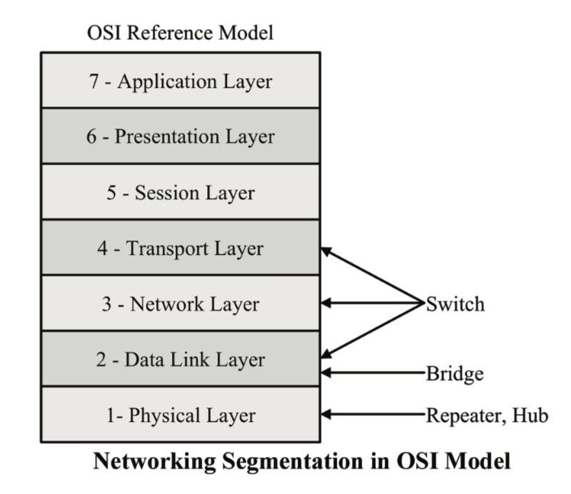
The backbone of a computer network uses several types of devices for interconnection: Repeaters, hubs, bridges, switches, and routers.
Each is important and serves a different role in facilitating communication between networked computers.
The terms hub, bridge, switch, and router are often used interchangeably and misused, but, in fact, the devices are quite different.
The difference in functionality can also be described through their access to the OSI 7 Layer Model, as shown in the image above.
Note: Theoretically, the total Ethernet network expansion is 5,120 m or roughly 15,400 feet, limited by the signal propagation time which must be below the Ethernet slot time of 51.2 microseconds (based on 100 Mbit/sec). A violation of that rule will render CSMA/CD (Carrier Sense Multiple Access / Collision Detect) dysfunctional and message collisions will occur undetected.
Repeaters
Repeaters are primarily used as signal conditioners (accessing Layer 1 – Physical Layer) to increase the usable physical length between devices (network diameter), but, in fact, they are not segmentation devices. They receive an Ethernet packet, amplify the signal, and transmit the packet. Repeaters do not reduce message collisions.
Hubs
Hubs, acting at the physical layer (Layer 1) of the OSI model, represent the most basic version of a segmentation device, and they are essentially repeaters that connect multiple devices over the same, shared medium.
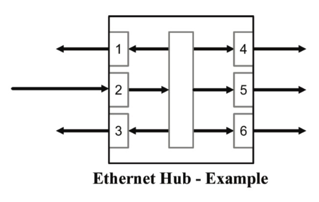
A hub broadcasts any data it received to its dedicated Ethernet network segment, i.e., an Ethernet data frame received through one port is, after being amplified, transmitted simultaneously to all other ports. In this scenario, the hub does not determine the receiver of the data frame. The receiving ports (nodes), in turn, decide individually whether or not the data is needed for their purposes.
The lack of intelligence in a hub reflects in its meager design requirements compared to other devices, but the basic functionality is mostly prohibitive for more extensive networks. The main reason is that hubs cannot rectify insufficient response times in a crowded and busy network because it does not reduce data traffic and message collisions.
Note: There is a limitation on the number of hubs that can be connected in series. More than two hubs (the allowed maximum is four) connected in series will negatively impact the CSMA/CD bus arbitration functionality.
However, due to their low-level design requirements (simple forwarding of messages) hubs (and also repeaters) provide the shortest delay times compared to bridges and switches.
Bridges
A bridge, in its basic form, connects two networks, increasing the network diameter as a hub does, but a bridge also regulates data traffic. Like a hub or a repeater, a bridge echoes what it receives from other stations, i.e., it does not create any traffic on its own. However, a bridge can learn which computers are connected to which network segment. Using that information, the bridge filters data packages by looking at the destination address of the package before sending it. If the destination address is not on the other side of the bridge, it will not transmit the data.
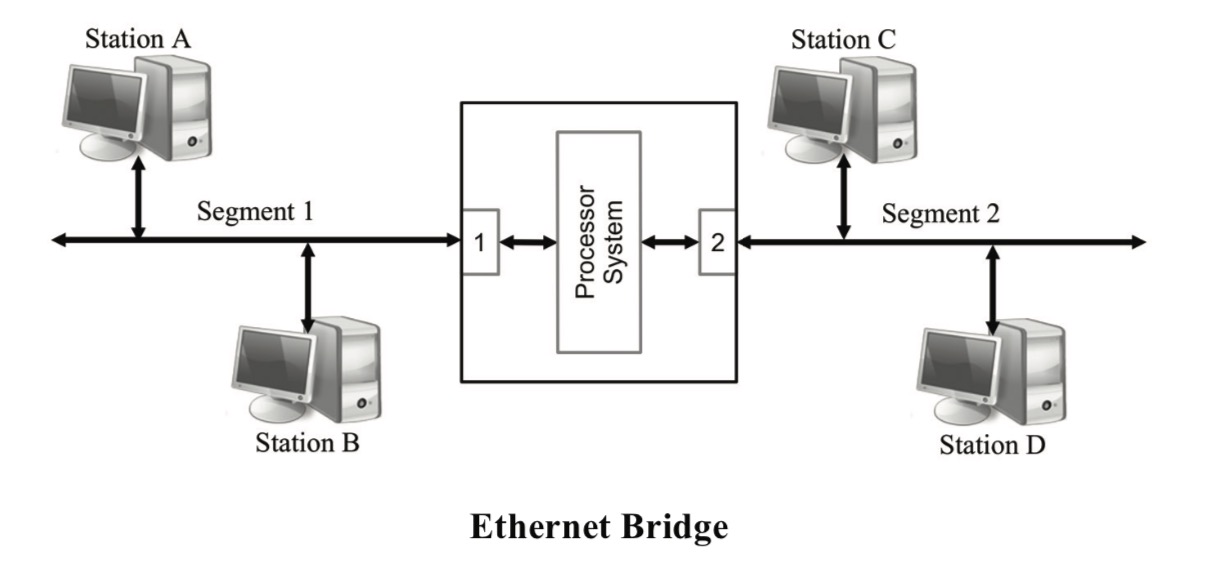
To learn which addresses are in use and to which port the computers are connected, the bridge observes the headers of the received Ethernet frames. It does so by examining the MAC source address of each received frame and recording the port through which it was received.
As a result, a bridge not only reduces unnecessary traffic; it also reduces the occurrence of bus arbitrations (CSMA/CD). Bridges also reduce congestion by allowing multiple conversations to occur on different segments simultaneously.
As expected, bridges forward broadcast frames (i.e., a data frame intended for all nodes in the network) to the other port. When a large number of nodes in the network broadcast data through a bridged network, congestion can be as bad as without using a bridge.
Another downside is that multicast frames (i.e., a data frame intended not for all but several nodes in the network) are handled in the same way as broadcast messages. This will create unnecessary traffic to nodes that have no use for the data. Some bridges implement extra processing to control the flooding of multicast frames.
Switches
It must be reiterated that the terms for network segmentation devices are often used interchangeably and misused, and that is definitely (and quite often) the case with bridges and switches.
Per definition, a bridge connects only two network segments, i.e., it has only two ports. A switch provides the same functionality as a bridge, but it steps up on a bridge in that it controls multiple ports. This narrow definition may appear as mere semantics, but, in all consequence, you bridge only two points, and you switch between multiple points.

Although switches are typically Layer 2 (Data Link Layer) devices, there are advanced versions capable of performing switching operations based on data from Layer 3 (Network Layer) and Layer 4 (Transport Layer).
Layer 3 Switches can operate on information provided by the Internet Protocol (IP), such as IP Version, source and destination address, or type of service.
Layer 4 Switches can switch by source and destination port and information from higher-level applications.
Further refinements of the IEEE 802 standards (i.e., specifically those for switch operations) define how these switches deal with prioritization, i.e., priority determination, queue management, and more. These refinements are of advantage for boosting the real-time performance of Industrial Ethernet applications.
However, these standards come with their drawbacks, such as increased hardware costs and compatibility issues with legacy Ethernet networks. Industrial-strength switches, in general, are costly, and in some cases, the manufacturer cannot guarantee the operational predictability.
Note: Switches add latency per message to a network (according to current technology 7.5 microseconds in the best case; more than 10 microseconds is standard). The impact on the cycle time depends on the network load. In all consequence, Ethernet switches are disadvantageous when it comes to achieving hard real-time performance.
The impact of hubs on the cycle time is minimal (~ 500 nanoseconds).
TCP/IP Illustrated, Volume 1: The Protocols
TCP/IP Illustrated, Volume 1, Second Edition, is a detailed and visual guide to today’s TCP/IP protocol suite. Fully updated for the newest innovations, it demonstrates each protocol in action through realistic examples from modern Linux, Windows, and Mac OS environments. There’s no better way to discover why TCP/IP works as it does, how it reacts to standard conditions, and how to apply it in your applications and networks.
Building on the late W. Richard Stevens’ classic first edition, author Kevin R. Fall adds his cutting-edge experience as a leader in TCP/IP protocol research, updating the book to reflect the latest protocols and best practices fully. He first introduces TCP/IP’s core goals and architectural concepts, showing how they can robustly connect diverse networks and support multiple services running concurrently. Next, he carefully explains Internet addressing in both IPv4 and IPv6 networks. Then, he walks through TCP/IP’s structure and function from the bottom up: from link layer protocols–such as Ethernet and Wi-Fi–through the network, transport, and application layers.
 Loading... Please wait...

