Blog
Recent Posts
CAN Bus Programming in Python for Automotive, Industrial Automation, and Robotics
Posted by on
 The Controller Area Network (CAN bus) is a resilient, lightweight, and efficient communication protocol originally developed by Bosch in the 1980s for in-vehicle networks. It allows multiple microcontrollers (ECUs) and devices to communicate without a central host, using a multi-master, message-oriented design. Over the decades, CAN bus has expanded beyond its automotive roots into domains like industrial automation, robotics, and even marine systems. Today it remains a de facto standard in vehicles and is common in machinery that requires reliable real-time communication between electronic components.
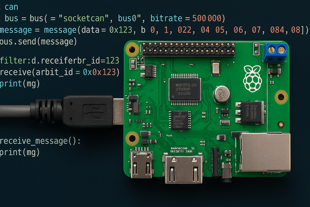
Python provides a beginner-friendly yet powerful way to program CAN bus applications. On platforms like the Raspberry Pi, using Python together with CAN interface hardware has become one of the most accessible methods to prototype or implement CAN-based systems. In particular, the combination of a Raspberry Pi with a specialized CAN interface HAT (Hardware Attached on Top) such as Copperhill Technologies' PiCAN series allows users to send and receive CAN messages in Python with ease. This report presents a comprehensive overview of CAN bus programming in Python, and explores how it is applied in automotive diagnostics, industrial automation, and robotics. We also explain the role of PiCAN CAN Bus HATs in interfacing a Raspberry Pi with CAN networks, enabling rapid development and integration into these applications.
Understanding CAN Bus Basics
CAN bus is a multi-master serial bus standard designed for robust real-time communication in embedded systems. All nodes on a CAN network can transmit messages, and message arbitration (priority-based access) ensures deterministic delivery even under high bus load. A CAN message (frame) contains an identifier (which also represents priority), data bytes, and CRC for error detection. Key features that make CAN suitable for automotive, industrial, and robotic systems include:
-
Reliability and Error Handling: CAN automatically detects transmission errors and supports retransmission. Its built-in error-handling and fault confinement mechanisms contribute to high reliability in noisy environments.
-
Real-Time Determinism: The priority arbitration mechanism guarantees that critical messages (e.g. a brake command) get bus access before lower-priority traffic, which is crucial for real-time control systems.
-
Reduced Wiring Complexity: Multiple ECUs share the same two-wire bus (CAN High and CAN Low), reducing the wiring harness compared to point-to-point links. This simplifies design and lowers cost while still allowing any node to communicate with any other.
-
Robustness in Harsh Environments: CAN’s differential signaling and noise immunity make it ideal for automotive and industrial settings where electromagnetic interference and long cable runs are common.
Originally popularized in cars, trucks, and buses, these advantages have led CAN to be widely adopted in factory automation equipment, medical devices, agricultural and construction machinery, robotics, and more. Several higher-layer protocols exist on top of CAN (for specialized domains), such as OBD-II for car diagnostics, SAE J1939 for heavy vehicles, CANopen and DeviceNet for industrial automation, and NMEA 2000 for marine systems. Understanding the basics of CAN bus provides a foundation for leveraging it in Python applications across these fields.
Python for CAN Bus Programming
Python offers an easy-to-use environment for interfacing with CAN hardware, making it attractive for both beginners and rapid prototyping. On Linux systems like Raspberry Pi, CAN interfaces are typically exposed via SocketCAN, the Linux kernel's native CAN support. SocketCAN presents CAN ports as network interfaces (e.g. can0), allowing Python programs to treat CAN messages similar to network packets. This integration brings several benefits:
-
Developers can use simple Linux utilities (candump, cansend, ip link, etc.) to test or configure CAN, and then harness the same interface in Python code.
-
High-level libraries like python-can provide a uniform API to send/receive CAN messages and handle different CAN hardware. The python-can library abstracts away device specifics and runs anywhere Python does – from PCs with USB-CAN adapters down to embedded Linux boards like the Raspberry Pi.
-
Common tasks such as logging CAN traffic or injecting test messages can be accomplished in just a few lines of Python. For example, one can passively monitor vehicle data from the OBD-II diagnostic port using Python, or send commands to test an ECU, without needing low-level C code. This lowers the entry barrier for automotive diagnostics and experimentation.
-
Python’s integration with SocketCAN means it can leverage powerful analysis tools: for instance, a Python script can capture CAN frames and these can be opened in Wireshark for debugging, or Python can replay recorded bus data for simulation purposes.
Python’s simplicity is a major advantage in CAN bus development. Beginners can quickly write scripts to parse sensor data or generate CAN messages, while intermediate users can develop more complex logic (e.g., decoding higher-layer protocols or implementing custom CAN-based communication) without dealing with memory management or real-time OS programming. This allows focus on the application itself rather than low-level details. However, it’s worth noting that Python is not a real-time language – time-critical control loops may still require dedicated microcontroller logic. In many scenarios, though, Python is fast enough to handle diagnostics, data logging, configuration tasks, and supervisory control in automotive and robotics projects. It is especially powerful when combined with the right hardware interface, such as the PiCAN HAT, which we discuss next.
Interfacing with CAN Networks using PiCAN HATs
PiCAN HATs by Copperhill Technologies are add-on boards for the Raspberry Pi that provide professional-grade CAN bus connectivity. These boards contain a CAN controller (such as the Microchip MCP2515 or MCP2517FD) and a transceiver, effectively equipping the Raspberry Pi with one or more CAN bus ports. The PiCAN HATs attach to the Pi’s GPIO header and communicate via SPI, and each board supports the SocketCAN driver for easy installation and use in Linux. In practice, this means once the HAT’s driver is installed, the CAN interface appears as a network device (can0, can1, etc.), and can be accessed by Python programs (or C/C++ programs) without any custom kernel development. Copperhill provides many examples and references, making it straightforward even for newcomers to get started with CAN on the Raspberry Pi using PiCAN hardware.
Popular PiCAN models:
-
PiCAN2: A single-channel CAN bus HAT based on the MCP2515 controller. It is suitable for basic CAN communication in automotive or robotics systems and includes a standard CAN transceiver (MCP2551).
-
PiCAN2 Duo: A dual-channel CAN HAT offering two independent CAN ports. Ideal for bridging or gateway applications where the Pi might need to listen and talk on two CAN networks simultaneously.
-
PiCAN3: An enhanced HAT designed for the Raspberry Pi 4, using the MCP2515 CAN controller. It supports Classical CAN (CAN 2.0B) at speeds up to 1 Mbps. It does not support CAN FD.
- PiCAN-FD: The PiCAN FD board adds advanced CAN Bus FD (Flexible Data-Rate) capabilities to the Raspberry Pi, making it ideal for industrial, automotive, and embedded networking applications.
-
Isolated Versions: Some PiCAN models include galvanic isolation on the CAN port, protecting the Pi and attached equipment from voltage spikes or ground loops in industrial environments.
-
Specialized Versions: Models tailored for marine (e.g., PiCAN-M) and GPS-enabled logging use cases, as well as versions with onboard switching power supplies (SMPS).
The core role of a PiCAN HAT is to serve as the bridge between the Raspberry Pi (and your Python code) and the CAN network. By handling the low-level CAN protocol in hardware and presenting a standard interface to the OS, PiCAN boards let developers focus on higher-level logic.
Applications in Automotive Diagnostics and Telemetry
In modern vehicles, CAN bus connects critical systems (engine, transmission, brakes, etc.) as well as convenience and infotainment modules. Automotive diagnostics refers to accessing this network to monitor sensor values, retrieve fault codes, or even reprogram modules. Python, combined with a PiCAN-equipped Raspberry Pi, is a powerful tool in this domain for hobbyists and professionals alike.
Typical use cases:
-
Vehicle Diagnostics: Reading diagnostic trouble codes, live engine data, or VIN information via OBD-II.
-
Telemetry and Data Logging: Recording CAN messages for analysis or real-time streaming.
-
Aftermarket ECU/Dashboard Development: Prototyping communication with vehicle systems or displaying data on custom interfaces.
-
Electric Vehicle Prototyping: Interfacing with BMS or motor controllers using CAN FD where needed.
Python makes these tasks accessible without requiring deep knowledge of embedded C or automotive-grade tools.
Applications in Industrial Automation
Industry often relies on fieldbus networks like CANopen and DeviceNet for communication between PLCs, sensors, and actuators. Python and PiCAN enable:
-
Gateway Systems: Bridging legacy CAN systems with Ethernet or MQTT.
-
Logging and Analysis: Capturing CAN traffic to identify faults or optimize performance.
-
Diagnostics and Monitoring: Reading statuses or sensor data from PLC-controlled networks.
-
Simulation and Testing: Emulating CANopen nodes or generating traffic for validation.
Python-based CAN systems support integration of legacy equipment into modern IoT platforms, all while running on low-cost Raspberry Pi hardware.
Applications in Robotics
Robots often involve distributed control across components such as actuators, sensors, and controllers. Python and PiCAN are used for:
-
Distributed Control: Coordinating components via real-time messaging.
-
CANopen Control of Actuators: Managing robotic arms and joint modules.
-
Swarm Coordination: Managing communication among multiple robots using CAN FD.
-
Rapid Development: Testing control algorithms and sensor interactions in Python.
This enables researchers, educators, and startups to build scalable and responsive robotic platforms.
Conclusion
CAN bus programming in Python opens up a world of possibilities for implementing and experimenting with distributed systems in automotive, industrial, and robotic domains. By abstracting low-level details, Python allows beginners and intermediate programmers to engage with CAN networks using simple scripts, yet it remains powerful enough to build full-fledged tools for professionals. The Copperhill PiCAN series of Raspberry Pi HATs plays a pivotal role in this landscape by bridging the gap between the raw CAN bus and user-friendly development. These HATs provide the Raspberry Pi with immediate CAN capabilities and, with SocketCAN support, ensure that integrating CAN communication is as straightforward as standard network programming. Whether one is building an in-vehicle diagnostic scanner, a custom CAN-based robot controller, or a gateway between industrial machines, the combination of PiCAN hardware and Python software yields a scalable, reliable, and cost-effective solution.
References
-
Voss, W. (2025). CAN Bus Applications in Automotive, Marine, Robotics, and Industrial Systems Using the PiCAN Series of HATs for Raspberry Pi. Copperhill Technologies.
-
Copperhill Technologies. PiCAN CAN Bus HAT for Raspberry Pi – Selection Guide.
-
Python Software Foundation. python-can Documentation (v4.6.1).
-
Copperhill Technologies. Installing python-can on the Raspberry Pi.
-
Anderson, M. (2021). TMotorCANControl: Python library for TMotor actuators.
-
Voss, W. (2021). PiCAN CAN Bus HAT for Raspberry Pi – Introduction.
-
Falch, M. (2025). CAN Bus Explained – A Simple Intro. CSS Electronics Guides.
Mastering CAN Bus: A Deep Dive into Automotive CAN Bus and In-Vehicle Networks
In an age when vehicles are less about purely mechanical linkages and increasingly about interconnected electronics and networks, the book Automotive CAN Bus and In-Vehicle Networks arrives at exactly the right moment. Graham Stoakes presents what he calls “the digital nervous system of modern vehicles” — and for technicians, students, and enthusiasts alike, this translates [...]
 Loading... Please wait...


