Recent Posts
CAN Bus Prototyping With Arduino Uno - Arduino CAN Shields
Posted by on
This post is part of a series about Controller Area Network (CAN Bus) Prototyping With the Arduino Uno.
Since Controller Area Network (CAN) is predominantly targeted at industrial solutions (versus the vastly more popular USB for non-industrial use such as home and lab), there aren’t too many choices available in the market.
Through some research (i.e. browsing) I found two very similar solutions, and they both work with the same CAN library. Both solutions use the Microchip MCP2515 CAN controller. Also, both solutions are distributed through worldwide online resources.
The Microchip MCP2515 CAN Controller
Microchip Technology’s MCP2515 is a stand-alone Controller Area Network (CAN) controller that implements the CAN specification, version 2.0B. It is capable of transmitting and receiving both standard and extended data and remote frames. The MCP2515 has two acceptance masks and six acceptance filters that are used to filter out unwanted messages, thereby reducing the host MCUs overhead. The MCP2515 interfaces with microcontrollers (MCUs) via an industry standard Serial Peripheral Interface (SPI).
The features include two receive buffers with prioritized message storage, six 29-bit filters, two 29-bit masks, and three transmit buffers with prioritization and abort features. (Source: Microchip Datasheet)
Note: CAN specification 2.0B refers to the capability of using standard CAN frames with 11-bit message identifier plus the extended format with a 29-bit message ID.
To download the full MCP2515 datasheet log on to:
http://ww1.microchip.com/downloads/en/DeviceDoc/21...
Both CAN shields as described in the following chapters utilize the Microchip MCP2551 CAN transceiver, which converts the internal TTL signals to a differential voltage as demanded by the CAN standard.
To download the full MCP2551 datasheet log on to:
http://ww1.microchip.com/downloads/en/DeviceDoc/21...
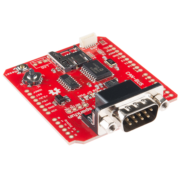
Arduino CAN-Bus Shield by Sparkfun
The CAN-BUS Shield provides your Arduino with CAN Bus capabilities and allows you to hack your vehicle.
This shield allows you to poll the ECU for information including coolant temperature, throttle position, vehicle speed, and engine rpms. You can also store this data or output it to a screen to make an in-dash project.
It uses the Microchip MCP2515 CAN controller with the MCP2551 CAN transceiver. CAN connection is via a standard 9-way sub-D for use with OBD-II cable.
Ideal for automative CAN application. The shield also has a uSD card holder, serial LCD connector and connector for an EM506 GPS module. These features make this shield ideal for data logging application.
Features
- CAN v2.0B up to 1 Mb/s
- High speed SPI Interface (10 MHz)
- Standard and extended data and remote frames
- CAN connection via standard 9-way sub-D connector
- Power can supply to Arduino by sub-D via resettable fuse and reverse polarity protection.
- Socket for EM506 GPS module
- Micro SD card holder
- Connector for serial LCD
- Reset button
- Joystick control menu navigation control
- Two LED indicator
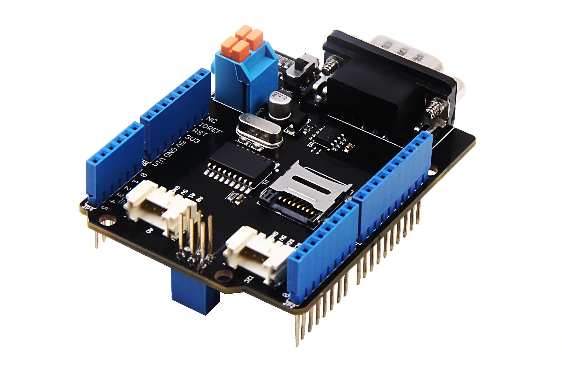
CAN-BUS Shield by Seeed Studio
The CAN-BUS Shield V2 uses the MCP2515 as a CAN Bus controller and the MCP2551 as a CAN Bus transceiver. OBD-II or CAN Bus standard pinout can be selected by switching jumpers on DB9 interface, the default pinout is OBD-II.
Secondly they added a TF card slot for data storage and the CS pin can be either set to D4 or D5. The INT pin can also be set to D2 or D3 by switching jumpers on the back of the shield. If you want to use more than 2 CAN-BUS Shield, it is needed to cut P1 pad. In V2, they moved the P1 pad from front to the back of the shield to make it easier to cut and solder. All in one, there are many options for customization.
Consider that the D0/D1 pin are usually used for downloading code, we changed the serial Grove connector to pin A0/A1. The I2C grove connector is also changed to more reasonable standard SDA/SCL pin instead of previous A4/A5. The two grove connectors are both changed to horizontal rather than vertical to the shield so that it would be more convenient when connecting to other grove modules.
Features
- Implements CAN V2.0B at up to 1 Mb/s
- Industrial standard 9 pin sub-D connector
- OBD-II and CAN standard pinout selectable.
- Changeable chip select pin
- Changeable CS pin for TF card slot
- Changeable INT pin
- Screw terminal that easily to connect CAN_H and CAN_L
- Arduino Uno pin headers
- 2 Grove connectors (I2C and UART)
- SPI Interface up to 10 MHz
- Standard (11 bit) and extended (29 bit) data and remote frames
- Two receive buffers with prioritized message storage
 Loading... Please wait...


