 Loading... Please wait...
Recent Posts
CAN Bus Prototyping With Arduino Uno - A Simple CAN Bus Network Monitoring and Diagnostics Program
Posted by on
This post is part of a series about Controller Area Network (CAN Bus) Prototyping With the Arduino Uno.
The Arduino board in combination with the CAN Bus shield provides the hardware for a full-fledged CAN network monitoring tool, and this next Arduino program is a first step in that direction.
However, before we get into more detail, let me issue some warnings regarding possible restrictions of the system:
- The MCP2515 has only two receive buffers, which limits the system’s capabilities to respond in a timely fashion while receiving and processing the data traffic. For high-speed, high-busload applications, it is recommended to use the message filter functions to reduce the processing load on the CPU.
- Besides the limited processing speed of the 8-bit CPU, the Arduino Uno comes with only 32 kByte program memory, which is sufficient for a great number of small applications. However, when it comes to more demanding tasks such as a CAN Bus monitoring tool, the memory resources may be exhausted quicker than expected. For instance, the following application already uses roughly 20 percent of the total memory space, and it provides only a very rudimentary version of a monitoring tool.
In all consequence, if you are serious about creating a more-or-less professional application, you might want to consider alternative hardware solutions such as the Arduino Due.
In order to create a CAN Bus monitoring system, we need to:
- Receive CAN Bus messages and display them
- Be able to enter CAN Bus messages and transmit them
With the previous two programming samples in mind, we have already accomplished step #1, but the next step (entering CAN Bus messages) needs a bit more work.
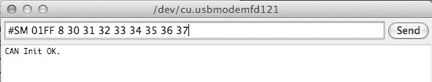
The idea is to enter the CAN Bus message into Arduino’s serial monitor and transmit the result by clicking the Send button. In order to accomplish that, we need to follow a data entry format as shown in the following.
Command: Send CAN Message (11 bit)
Description: Node
receives a message and transmits it into the CAN bus
Format: #SM
id n dd dd….
id
= Message ID (2 bytes, hex)
n = Number of bytes (1 byte, 0 to 8)
d = data bytes (hex, up to eight bytes)
Example:
#SM
01FF 8 30 31 32 33 34 35 36 37
In this previous example, we design a CAN message with an ID of 01FF and a data length of 8 bytes. These 8 bytes are represented by the number 30 (hex) to 37, which is the equivalent of ASCII-0 to ASCII-7.
While the basic functionality of sending and receiving CAN messages remains the same, the program size and complexity has, naturally, grown. Most of the code, however, is being used for conversion between hex and ASCII formats (for readability) and some rudimentary syntax check.
Note: The data entry in this following programming sample is not fool-proof, meaning, while the program does some syntax checks, it is still possible that incorrect data entries will still be interpreted as valid CAN message formats.
Also, this example still uses 9600 baud for the communication with Arduino’s serial monitor. A faster transmission speed is recommended for CAN networks with high data traffic.
Due to the large size, I have not included the source code in this post, but please feel free to download the Arduino project (zip file) to inspect the code.
Without going into the last detail, here is a brief description of the code:
The setup() function remains the same as in the first two programming examples in this book, i.e. it handles the initialization of the serial connection and the CAN Bus controller.
The loop() routine, however, looks extremely simple, but that only means that the major part of the functionality has been distributed to a number of new functions.
Inside loop() are only two function calls:
- SubCheckCANMessage() checks for a received CAN Bus message and displays it on the Arduino serial monitor.
- SubSerialMonitorCommand() receives a string from Arduino’s serial monitor, achieves some rudimentary syntax check, and sends out the CAN Bus message.
The remaining function calls are:
- nFctReadSerialMonitorString() reads the data format string as entered by the user and returns the string length.
- nFctCStringInt() converts a string into integer and returns the integer data.
- lFctCStringLong() converts a string into long and returns the long data.
Note: Unlike C#, the C and C++ programming languages provide only limited support for data conversion, and sometimes writing your own conversion functions fits your application needs better than the provided library functions.
The following shows screen shots taken trough a session with this programming example:
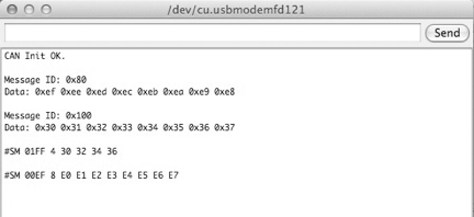
First, we received two CAN messages (IDs 0x80 and 0x100), then we sent two CAN Bus messages (IDs 01FF and 00EF).
For this operation, I used my standard test configuration (i.e. USB-to-CAN gateway with Windows monitoring tool as the second CAN Bus node), but from here on, it is possible to use two Arduinos with CAN Bus shield running the same application.
In order to extend the functionality of this programming example, the following commands would be helpful to provide a full-fledged monitoring and diagnostics tool:
- CAN Start/Stop – Starts or stops displaying messages on the Arduino serial monitor.
- CAN Baud Rate – Modify the CAN baud rate.
- Request CAN Settings – Reports the current settings such as baud rate and message ID mode.
- Send CAN Message in 29-bit format.
- Add CAN Message Filter
- Delete CAN Message Filter
- Delete All CAN Message Filters
And yes, there are multiple possibilities of extending this program toward a really professional version. However, what the Arduino cannot provide is a professionally looking graphical user interface, and this is where the existing USB connection to a PC opens the door to more possibilities.