 Loading... Please wait...
Recent Posts
SAE J1939 Programming with Arduino - J1939 Network Scanner
Posted by on
This post is part of a series about SAE J1939 ECU Programming & Vehicle Bus Simulation with Arduino.

Just like the previous project (See chapter Receiving and Responding to J1939 Request Frames) we will be using the SAE J1939 Request Message, in this case to inquire node addresses from the vehicle network.
The Request Message (a.k.a. the Request for Address Claimed Message) is also used during the address claim process as defined in SAE J1939/81.
Our network scanner project is very similar to the address claim process, since we are inquiring addresses from the network (The address claim process will inquire specific addresses to see if they are taken or not).
Note: Yet again, this sample project will only work with two nodes, one Arduino loaded with the following project plus a second node loaded with the full ARD1939 – SAE J1939 Protocol Stack for Arduino (See also chapter ARD1939 – Implementation).
Let’s have another look at the Request for Address Claimed Message:
- PGN 59904 – Request for Address Claimed Message
- Parameter Group Number: 0xEAxx (where xx represents the destination address, either the global address 255 for broadcasting, or the specific node address)
- Data Length: 3 bytes
- Data: Bytes 1, 2, 3 = Requested PGN (LSB first, MSB last)
- Default Priority: 6
The Request for Address Claimed message (when using a full protocol stack with its address claim procedure) is used to request the sending of an Address Claimed message from either a particular node in the network or from all nodes (use of global destination address = 255). The Address Claimed message (as described in the following) will provide the requested information, i.e. address and NAME of the responding node(s).
The purpose of sending such a request may be for several reasons, for instance:
- A node is checking whether or not it can claim a certain address.
- A node is checking for the existence of another node (Controller Application) with a certain function.
The response to a Request for Address Claimed message can be multiple:
- Any addressed node that has already claimed an address will respond with an Address Claimed message.
- Any addressed node that was unable to claim an address will respond with a Cannot Claim Address message.
- Any addressed node that has not yet claimed an address should do so by responding with their own Address Claimed message where the source address is set to NULL (254).
- A node sending the Request for Address Claimed message should respond to its own request in case the global destination address (255) was used.
The response to the Request for Address Claimed message is the actual Address Claimed message as defined in the following:
- PGN 60928 – Address Claimed Message
- Parameter Group Number: 0xEExx (where xx represents the destination address, either the global address 255 for broadcasting, or the specific node address)
- Data Length: 8 bytes
- Data: NAME of the control application (See also chapter SAE J1939/81 - Address Claim Procedure
- Default Priority: 6
The code for our current Arduino project, the Network Scanner, is, yet again, fairly simple:
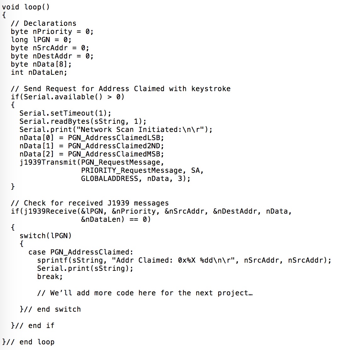
- As soon as the user enters an input through the serial monitor, we transmit the Request for Address Claimed message. We use the global address (255) to receive responses from all nodes in the network.
- We check the CAN interface for a received J1939 data frame.
- If a message was received, we check if it was an Address Claimed message.
- If the message was the Address Claimed message, we print the address as received.
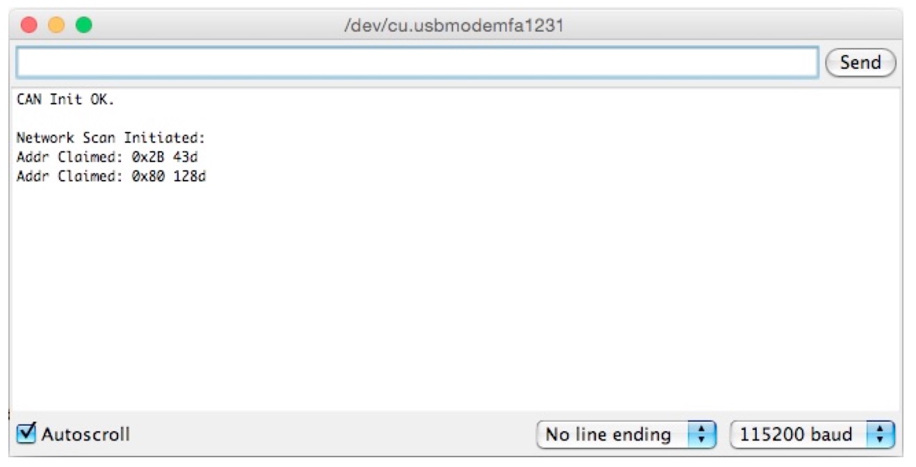
My configuration allowed me to connect two SAE J1939 nodes to the network, an ARM system at address 0x2b (43) and an Arduino Mega 2560 at address 0x80 (128).
The following screen shot from the aerial monitor confirms the configuration and the addresses:
As another proof of concept, let’s have another look at the ADFweb analyzer software, which I have always connected:
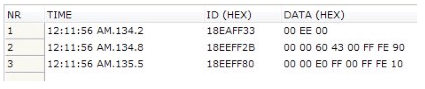
- Line 1: Our Arduino application sends out the Request for Address Claimed message. Note the ID where 18 indicates a priority of 6, EAFF represents the Request for Address Claimed message including the global address 255 (0xFF). The last byte of 0x33 represents the simulated source address of our application. The data field contains the three-byte PGN for Address Claimed message (00E000; LSB first, MSB last).
- Line 2: The node at address 0x2B (43) responds with the Address Claimed message. Note the ID where 18 indicates a priority of 6, EEFF represents the Address Claimed message including the global address 255 (0xFF). The last byte represents the node’s source address. The data field contains the eight-byte NAME of the control application (ECU).
- Line 3: Same as line 2 but different address and NAME.
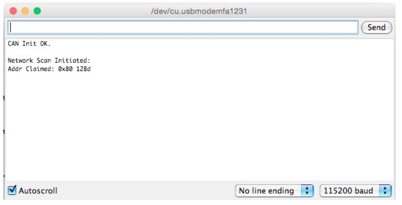
In a next step, to demonstrate the difference between message broadcasting and peer-to-peer, I replaced GLOBALADDRESS in the j1939Transmit function with 0x80, which means that we are checking the network for the existence of one particular address.
The result on the Arduino serial monitor is not very impressive after all; it shows (as expected) only one response:
The ADFweb CAN analyzer software, however, reveals more detail about the peer-to-peer (node to node) communication:
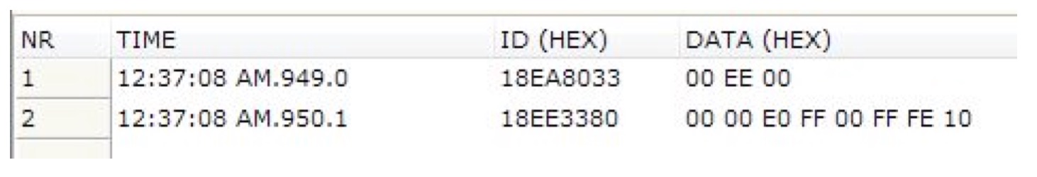
- Line 1: Our Arduino application sends out the Request for Address Claimed message. Note the ID where 18 indicates a priority of 6, EAFF represents the Request for Address Claimed message including the inquired address 0x80 (128). The last byte of 0x33 represents the simulated source address of our application. The data field contains the three-byte PGN for Address Claimed message (00E000, LSB first, MSB last).
- Line 2: The node at address 0x80 (128) responds with the Address Claimed message. Note the ID where 18 indicates a priority of 6, EE33 represents the Address Claimed message including the requestor address 0x33. The last byte represents the node’s source address. The data field contains the eight-byte NAME of the control application (ECU).

SAE J1939 has become the accepted industry standard and the vehicle network technology of choice for off-highway machines in applications such as construction, material handling, and forestry machines. J1939 is a higher-layer protocol based on Controller Area Network (CAN). It provides serial data communications between microprocessor systems (also called Electronic Control Units - ECU) in any kind of heavy duty vehicles. The messages exchanged between these units can be data such as vehicle road speed, torque control message from the transmission to the engine, oil temperature, and many more.
A Comprehensible Guide to J1939 is the first work on J1939 besides the SAE J1939 standards collection. It provides profound information on the J1939 message format and network management combined with a high level of readability.