 Loading... Please wait...
Recent Posts
CAN Bus Bridge (CAN-to-CAN) Application With Arduino Due
Posted by on
 Basically, there are two scenarios where a CAN Bridge application is of use:
1. Connecting two separate CAN Bus networks.
2. Network length extension.
While the first scenario is more or less self-explanatory, let's look a little closer into the network length extension: The physical CAN network length depends primarily on the CAN baud rate, i.e. the higher the transmission speed the shorter the usable network length.
For more detailed information, please refer to A Comprehensible Guide to Controller Area Network.
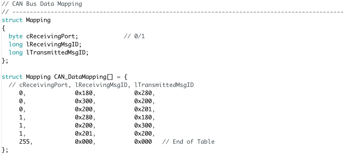
The trick with the CAN-to-CAN application is to receive higher-speed CAN messages on one port and transmit them at lower speed through the second CAN port, which effectively allows using extended physical network lengths. Please be aware that this method also requires some message filtering, since you can't squish all high-speed CAN messages into a slower network. Our application using the Arduino Due utilizes this by using a simple CAN message ID mapping table. This method also allows to assign new message IDs when it comes to preventing message ID collisions between two networks.
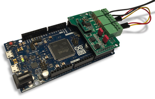
As a hardware I have been using our Arduino-Based ECU Development Board With Dual Bus Interface as shown in the image above.
As an alternative, you can also use your existing Arduino Due in combination with our Dual Can Bus Interface For Arduino Due.
The board is not an Arduino shield in the common sense. It incorporates dual CAN transceivers required by the two integrated CAN ports on the Arduino Due while allowing the operation with any Arduino-compatible shield that supports the necessary 3.3 VDC power requirements.
By combining our dual CAN port interface, the Arduino DUE microcontroller, an OBD2 or SAE J1939 cable, and open-source software libraries you are ready to go with powerful a turn-key Arduino-based dual CAN bus solution. Leverage the 32-bit processing capability of the Arduino DUE plus the built-in CAN ports for your next prototype.
Features
- 2 CAN ports with three-pin terminal connectors
- 3 LEDS (Power, CAN Activity Port 1, CAN Activity Port 2)
- Termination resistors switchable per jumper
But coming back to our project, let's have a look at the data mapping table that I filled with some random data:
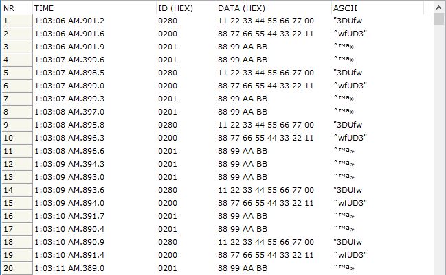
For my tests, I used another application using the same hardware setup (i.e. I used two Arduino Due with dual CAN interface), CAN Bus Data Traffic Simulation With Arduino Due. The sketch sends, among others, the message IDs 0x180, 0x300, and 0x200, which are translated according to the above shown table. All other message IDs are being ignored. The data traffic appears as shown here:
Click here to download the CAN-CAN_Bridge sketch (zip)...
Please feel free to contact me through the Contact Us page on this website in case you have questions or comments.