- Home
- Documentation
- jCOM1939 Monitor - Hardware And Driver Installation With jBoard-X2
jCOM1939 Monitor - Hardware And Driver Installation With jBoard-X2
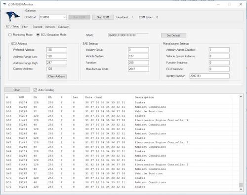
 The jCOM1939 Monitor Software is the perfect tool to monitor, analyze, and simulate SAE J1939 data traffic. The system combines our industrial-strength jBoard-X2 that functions as an SAE J1939 to USB (or RS-232) gateway. A comprehensive and easy-to-use, easy-to-understand Windows software displays not only SAE J1939 data traffic; it also allows to scan the network, simulate an ECU (incl. full node address negotiation features), and respond to data request messages.
- ECU Simulation Setup (Preferred Node Address, Negotiable Address Range, NAME, and more)
- Filter J1939 PGNs for Display
- Design J1939 PGNs for Transmission (Data and Request Messages)
- Design J1939 PGNs for Request Responses
- Scan a J1939 Network (Number of Nodes, Node IDs, NAMEs)
- Check Gateway Status (Error Messages, Software/Hardware Version)
- Set Gateway Parameters (Heartbeat Frequency, Message Acknowledgment)
- Free Updates (Click here to download)
jCOM1939 Monitor - Driver Installation
Most operating systems, such as Windows or Linux, will recognize the USB port and install the appropriate driver automatically. However, should that not be the case, please download the driver for your operating system as indicated below:
- Windows 7/8/8.1/10
- Windows XP/Server 2003/Vista/7/8/8.1
- Windows 2K
- WinCE 6.0
- WinCE 5.0
- Macintosh OSX
- Linux 3.x.x
- Linux 2.6.x
- Android (Application Note - PDF)...
jCOM1939 Monitor - Hardware Installation
The hardware installation is fairly easy and obvious.
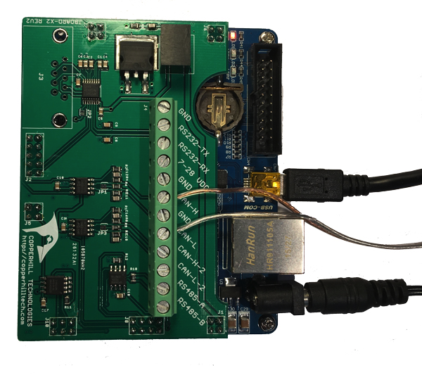
USB - Connect the Mini-USB cable as indicated below, i.e. use the USB port next to the Ethernet port.
CAN - The CAN connection is located on the terminal block. Use CAN channel 1 (CAN-L and CAN-H) - the board has two CAN channels but the software uses only one.
Power Supply - In most cases, the board can be powered through the USB port, meaning there would be no external power supply needed. However, depending on the hardware, specifically when you are using a USB hub or run the USB port on a laptop, you might run into problems getting the system going. It is therefore highly recommended to use the external 5VDC power supply, which is part of the delivery.

After powering up the board, you should see one LED permanently on, while another one blinks with a one-second frequency (heartbeat message).
The LEDs in the above image from top to bottom are:
- Power
- CAN bus activity
- USB port activity
After the drivers and hardware have been installed, please proceed with the software installation.
A Comprehensible Guide to J1939
SAE J1939 has become the accepted industry standard and the vehicle network technology of choice for off-highway machines in applications such as construction, material handling, and forestry machines. J1939 is a higher-layer protocol based on Controller Area Network (CAN). It provides serial data communications between microprocessor systems (also called Electronic Control Units - ECU) in any kind of heavy duty vehicles. The messages exchanged between these units can be data such as vehicle road speed, torque control message from the transmission to the engine, oil temperature, and many more.
The information in this book is based on two documents of the SAE J1939 Standards Collection: J1939/21 - Data Link Layer J1939/81 - Network Management A Comprehensible Guide to J1939 is the first work on J1939 besides the SAE J1939 standards collection. It provides profound information on the J1939 message format and network management combined with a high level of readability.
 Loading... Please wait...

