 Loading... Please wait...

Blog
Recent Posts
Understanding CAN Bus Error Frames: A Practical Guide to Diagnosing CAN Network Problems
Posted by on
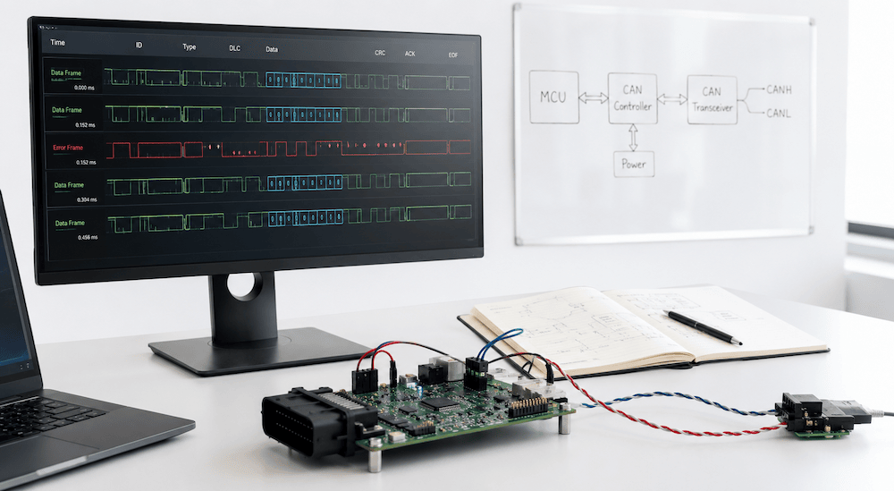 When you first connect a new CAN Bus network, everything usually works perfectly—until it doesn't.
Your firmware transmits messages, but nothing appears on the network. Your CAN controller reports transmit errors. Suddenly, the node enters Error Passive mode, and eventually Bus Off. Your analyzer may even display Error Frames, but it rarely explains why they occurred.
If this sounds familiar, you're not alone.
One of the biggest challenges for engineers new to CAN Bus development is understanding that an Error Frame is almost never the real problem. It is merely the network announcing that something else went wrong.
In this article, we'll explain what Error Frames are, why they occur, and—more importantly—how to systematically diagnose the underlying issue.
What Is an Error Frame?
Unlike a normal CAN data frame, an Error Frame does not carry application data.
Instead, it is a special sequence transmitted by a CAN controller whenever it detects that the current message has become invalid.
Think of it as the CAN Bus equivalent of someone interrupting a conversation and saying:
"Stop! Something is wrong. Ignore what was just transmitted."
Once an Error Frame appears:
-
the current message is discarded,
-
all nodes recognize the error,
-
the original transmitter automatically retries the message (provided it has not entered Bus Off). (CSS Electronics)
The Error Frame is therefore part of CAN's exceptional reliability. Rather than allowing corrupted data onto the network, CAN forces every node to agree that the frame must be retransmitted.
The Five CAN Error Types
Every Error Frame originates from one of five error detection mechanisms built into every CAN controller.
1. Bit Error
While transmitting, a node continuously monitors the bus.
If it sends a dominant bit but reads back a recessive bit (or vice versa), a Bit Error has occurred.
Typical causes include:
-
wiring faults
-
defective transceivers
-
incorrect bus termination
-
electrical noise
2. Stuff Error
CAN uses bit stuffing.
After five consecutive identical bits, the transmitter must insert a complementary bit.
If that rule is violated, receivers immediately detect a Stuff Error.
Common causes include:
-
signal distortion
-
timing errors
-
severe noise
-
faulty controllers
3. CRC Error
Each CAN frame contains a Cyclic Redundancy Check.
If the calculated CRC does not match the received CRC, the frame has been corrupted during transmission.
Usually caused by:
-
electromagnetic interference
-
poor wiring
-
marginal signal integrity
4. Form Error
Certain fields inside a CAN frame always have fixed values.
If any of these fields violate the CAN specification, every receiver recognizes a Form Error.
5. ACK Error
This one surprises many developers.
After transmitting a frame, the sender expects another node to acknowledge successful reception.
If nobody acknowledges the frame, the sender reports an ACK Error.
The important point:
An ACK Error does NOT necessarily indicate corrupted data.
It often simply means:
"Nobody else is listening."
This is extremely common during development.
The Most Common Development Mistakes
After helping countless engineers debug CAN systems, certain problems appear again and again.
Only One Node on the Bus
Perhaps the most common beginner mistake.
A CAN controller cannot successfully transmit by itself because no other node provides the ACK bit.
Result:
-
continuous ACK Errors
-
increasing transmit error counter
-
eventually Error Passive or Bus Off
Solution:
Always connect a second CAN node or a CAN interface acting as a listener.
Wrong Bit Rate
One node configured for:
500 kbit/s
Another configured for:
250 kbit/s
Neither node can understand the other.
Symptoms include:
-
constant Error Frames
-
transmit retries
-
Bus Off
Always verify that every device uses exactly the same nominal bit rate.
Missing Termination
CAN requires:
120 Ω at each physical end of the bus
Nothing more.
Nothing less.
Incorrect termination leads to:
-
reflections
-
distorted edges
-
CRC errors
-
Stuff Errors
-
intermittent failures
Reversed CANH/CANL
Fortunately, this problem is usually easy to diagnose.
Nothing works.
Transmit errors increase rapidly.
Always verify wiring before suspecting software.
Poor Grounding
Even though CAN is differential, nodes still require an appropriate common reference.
Ground problems frequently create intermittent errors that appear almost random.
Excessive Cable Length
Higher bit rates require shorter cables.
A network operating perfectly at:
125 kbit/s
may completely fail at:
1 Mbit/s
if the wiring exceeds recommended limits.
Understanding Error Counters
Every CAN controller maintains two internal counters:
-
Transmit Error Counter (TEC)
-
Receive Error Counter (REC)
These counters determine the controller's operating state.
| State | Typical Condition |
|---|---|
| Error Active | Normal operation |
| Error Passive | Error counters exceed threshold |
| Bus Off | Transmit Error Counter exceeds Bus Off threshold |
This fault confinement mechanism prevents one defective node from continuously disrupting the entire network. As transmit or receive errors accumulate, the controller gradually limits its own participation and may eventually disconnect itself from the bus until recovery is initiated. (Influx Technology)
A Practical Debugging Procedure
Whenever you encounter Error Frames, resist the temptation to immediately blame your firmware.
Instead, work through this checklist.
Step 1
Verify supply voltage.
Step 2
Measure the termination resistance.
Approximately 60 Ω between CANH and CANL with power removed indicates two 120 Ω terminators.
Step 3
Verify both nodes use identical bit timing.
Step 4
Confirm that at least two nodes are present.
Step 5
Check CANH/CANL polarity.
Step 6
Observe transmit and receive error counters.
Rapidly increasing TEC usually indicates the node cannot successfully place messages on the bus.
Step 7
If Bus Off occurs repeatedly, investigate the physical layer before modifying application software.
Why a CAN Interface Makes Development Much Easier
Many developers initially attempt to debug their firmware using only two embedded nodes.
Unfortunately, this provides very little visibility into what is actually happening on the network.
A professional CAN interface connected to a PC allows you to:
-
monitor all CAN traffic in real time
-
verify transmitted identifiers
-
inspect data bytes
-
confirm baud rate configuration
-
observe protocol activity
-
identify missing acknowledgements
-
record traffic for later analysis
-
inject test messages into the network
Instead of wondering whether your firmware is transmitting correctly, you can see exactly what is happening on the bus.
Copperhill CAN Interfaces for Development
The Copperhill Technologies product line includes a wide range of CAN Bus interfaces designed specifically for development, testing, and prototyping.
Depending on your application, you can choose from:
-
USB-to-CAN interfaces for Windows-based monitoring and diagnostics
-
Raspberry Pi CAN interfaces (PiCAN series) for embedded gateways, data loggers, and Linux development
-
Arduino, ESP32, and Teensy CAN boards for firmware development
-
CAN FD interfaces for next-generation applications requiring higher bandwidth
-
Ethernet-enabled CAN interfaces for remote monitoring and distributed systems
Whether you are bringing up a new ECU, testing industrial automation equipment, or developing a J1939 application, using a dedicated CAN interface dramatically shortens debugging time and provides valuable insight into network behavior that is difficult to obtain from firmware alone.
Final Thoughts
Error Frames often look intimidating when they first appear on a CAN analyzer.
In reality, they are evidence that the CAN protocol is doing exactly what it was designed to do: detect corrupted communication, prevent invalid data from propagating, and automatically recover whenever possible.
The key is to remember one simple principle:
An Error Frame is rarely the problem—it is the symptom.
By understanding the five CAN error types, monitoring the controller's error counters, and following a structured troubleshooting process, you can quickly determine whether the root cause lies in the wiring, timing, hardware, or software.
Once you develop that mindset, Error Frames become one of the most valuable diagnostic tools available during CAN Bus development rather than a source of frustration.
 Arduino IoT Cloud for Developers: Implement best practices to design and deploy simple-to-complex projects at reduced costs
Master the essential concepts of the Internet of Things (IoT) and build intelligent connected applications using the Arduino IoT Cloud, Arduino and ESP32 development boards, Amazon Alexa Voice Assistant, and MQTT—all through practical, hands-on projects.
Key Features
- Learn the Arduino IoT Cloud from the ground up with step-by-step, hands-on projects
- Develop a solid understanding of IoT application design, from fundamental concepts to advanced cloud integration
- Explore the Arduino IoT Cloud's features and capabilities for rapid prototyping and commercial IoT deployments
- Includes a complimentary PDF eBook with every print or Kindle purchase
Book Description
The Arduino IoT Cloud provides a powerful and accessible platform for developing connected devices while significantly reducing the time and cost required for prototyping, deployment, and maintenance. Whether you are a hobbyist, student, or professional developer, this practical guide takes you step by step through the complete Arduino IoT Cloud ecosystem.
Beginning with the fundamentals of IoT and cloud-connected devices, the book gradually introduces more advanced concepts through real-world projects using Arduino and ESP32 hardware. Along the way, you will learn how to connect devices to the cloud, monitor and control hardware remotely, integrate voice control with Amazon Alexa, and communicate efficiently using the MQTT protocol. By the end of the book, you will have the knowledge and practical experience needed to design, prototype, and deploy reliable IoT applications for both personal and commercial projects. More information...
Why CAN and LIN Need to Communicate in Modern Vehicles
At first glance, it may seem odd that a vehicle would use two different network technologies—CAN (Controller Area Network) and LIN (Local Interconnect Network)—and even stranger that they need to communicate with each other. After all, why not use one network everywhere and avoid the complexity? The truth is that both CAN and LIN exist because [...]