 Loading... Please wait...

Blog
Recent Posts
Physical Diagnostics of CAN Networks – Looking Beyond the Protocol
Posted by on
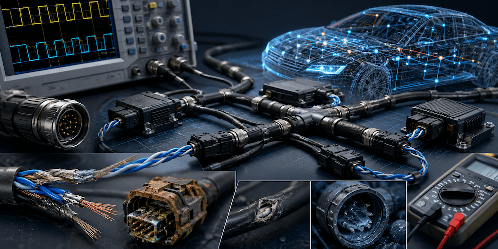 Most CAN Bus troubleshooting starts with software tools. Engineers connect a CAN analyzer, look at message traffic, verify identifiers, and search for protocol errors. While that approach is certainly useful, it often overlooks the most common source of CAN network problems: the physical layer.
The CAN protocol itself is remarkably robust. However, damaged cables, poor connectors, incorrect termination, excessive stub lengths, and electromagnetic interference can create symptoms that appear to be software or configuration issues. This is why physical diagnostics has become an increasingly important aspect of modern CAN network maintenance.
Why Physical Diagnostics Matters
A CAN controller can tell us that errors are occurring, but it cannot always explain why.
A node may repeatedly enter a bus-off condition. Error counters may increase rapidly. Messages may occasionally disappear. Network communication may become unreliable under specific operating conditions.
In many cases, the root cause is not a protocol problem at all. Instead, the issue originates somewhere within the physical network infrastructure.
Traditional CAN diagnostics often focus on:
- Message traffic
- Error frames
- Bus load
- Node behavior
- Protocol conformance
Physical diagnostics focuses on:
- Cable quality
- Signal integrity
- Connector condition
- Termination resistors
- Network topology
- Electromagnetic interference
- Reflection and ringing effects
These factors directly affect the quality of the electrical signals traveling through the network. A CAN system may appear operational while physical defects slowly degrade reliability until communication eventually fails.
The CAN Physical Layer
One of the reasons for CAN's success is its differential signaling method.
Instead of transmitting data on a single wire, CAN uses two conductors:
- CAN_H
- CAN_L
The receiver evaluates the voltage difference between the two wires rather than their absolute voltage levels. This design provides excellent immunity against electrical noise and interference. Twisted-pair wiring further improves noise rejection and signal robustness.
However, even a robust physical layer has limits.
Poor wiring practices, damaged cables, incorrect termination, or excessive network expansion can introduce reflections and distortions that affect communication quality.
Common Physical Layer Problems
Missing or Incorrect Termination
A properly designed CAN network requires two 120-ohm termination resistors located at the ends of the bus.
When measured with power removed, the resistance between CAN_H and CAN_L should be approximately 60 ohms because the two termination resistors appear in parallel.
Common mistakes include:
- Missing termination resistors
- Additional termination resistors
- Incorrect resistor values
- Termination located at incorrect positions
The result is signal reflection and reduced communication reliability.
Damaged Connectors
Connectors often represent the weakest point in a CAN installation.
Problems include:
- Corrosion
- Vibration damage
- Loose contacts
- Moisture intrusion
- Bent pins
These faults may produce intermittent communication failures that are notoriously difficult to reproduce.
Excessive Stub Lengths
Many engineers underestimate the impact of long branch connections.
Every stub acts as a miniature transmission line. At higher bit rates, especially in CAN FD systems, excessive stub lengths can introduce reflections that distort the signal. CAN FD networks are particularly sensitive because of their higher data phase bit rates.
Cable Damage
Physical damage can occur due to:
- Abrasion
- Crushing
- Rodent activity
- Improper installation
- Excessive bending
A cable may still conduct electricity while exhibiting degraded signal characteristics that create intermittent communication errors.
Looking at the Signal
One of the most effective diagnostic techniques is observing the actual CAN waveform.
An oscilloscope can reveal issues that are invisible at the protocol level.
Examples include:
- Signal reflections
- Ringing
- Excessive noise
- Voltage asymmetry
- Ground offset problems
A CAN analyzer may only report increasing error counters. An oscilloscope often reveals the underlying cause immediately.
This is especially important for CAN FD networks where higher data rates demand better signal quality and tighter control of network topology.
Measuring CAN Bus Health
Physical diagnostics commonly includes several straightforward measurements.
Termination Resistance
With power removed:
- Disconnect network power.
- Measure resistance between CAN_H and CAN_L.
- Expect approximately 60 ohms.
Values significantly above or below this range indicate termination problems.
Bus Voltage
With the network powered:
- CAN_H typically measures between 2.5 V and 3.0 V.
- CAN_L typically measures between 2.0 V and 2.5 V.
Abnormal voltage levels may indicate wiring faults, grounding issues, or damaged transceivers.
Transceiver Health
A damaged CAN transceiver frequently exhibits shorts to ground or power.
Measuring resistance from CAN_H and CAN_L to ground can often identify a failed interface device before more extensive troubleshooting becomes necessary.
CAN FD Raises the Stakes
Classical CAN networks are relatively forgiving.
CAN FD changes the situation significantly.
While CAN FD remains compatible with traditional CAN signaling principles, the higher data phase bit rates place greater demands on:
- Cable quality
- Termination accuracy
- Stub length control
- Connector integrity
- Signal integrity verification
A network that appears perfectly functional at 250 kbit/s may develop serious problems when upgraded to CAN FD at several megabits per second.
For this reason, physical diagnostics is no longer merely a troubleshooting activity. It has become an essential part of CAN FD network design and validation.
Modern Diagnostic Tools
Today's diagnostic equipment extends well beyond traditional CAN analyzers.
Modern tools can provide:
- Automatic baud-rate detection
- Termination measurements
- Bus voltage monitoring
- Error frame detection
- Oscilloscope functionality
- Traffic logging
- Signal quality analysis
The most advanced instruments combine protocol analysis and physical layer diagnostics in a single platform, enabling engineers to identify root causes much faster than with software analysis alone.
Final Thoughts
After working with CAN and SAE J1939 networks for many years, I have found that engineers often focus heavily on messages, identifiers, and protocol details while overlooking the physical layer.
Ironically, many communication problems have nothing to do with the protocol itself.
The CAN protocol is extraordinarily reliable. More often than not, the real culprit is a loose connector, damaged cable, improper termination resistor, excessive stub length, or poor signal integrity.
The lesson is simple: when troubleshooting a CAN network, start with the physical layer. A few minutes spent checking wiring, resistance, voltage levels, and signal quality can save hours of chasing software problems that never existed in the first place.
In CAN networking, the electrical layer is not merely the foundation—it is often where the truth is hiding.
 PiCAN3 CAN Bus Board for Raspberry Pi 4 with 3A SMPS And RTC
The PiCAN3 CAN Bus Board transforms a Raspberry Pi 4 into a powerful CAN networking platform suitable for automotive, industrial, and embedded control applications. Built around the proven Microchip MCP2515 CAN controller and MCP2551 CAN transceiver, the board supports CAN 2.0B communication at speeds up to 1 Mb/s. It provides flexible connectivity through both a standard DB9 connector and a screw-terminal interface, making it compatible with a wide variety of CAN-based systems. Developers can quickly begin working with CAN networks using the Linux SocketCAN framework and program applications in either C or Python.
What sets the PiCAN3 apart is its integrated 3-amp switch-mode power supply and real-time clock (RTC). The onboard power supply accepts 6 to 20 VDC input and can power both the Raspberry Pi and connected peripherals from a single source, making the board particularly useful in vehicle and industrial environments. Additional features include reverse-polarity protection, an onboard 120-ohm termination resistor, battery-backed RTC functionality, GPIO interrupt support, and compliance with the Raspberry Pi HAT standard. The result is a compact, reliable, and field-ready CAN Bus development platform for data logging, diagnostics, automation, and network monitoring projects. More information...
Error Reporting in SocketCAN with Specific Reference to the MCP2515 CAN Controller
SocketCAN is a set of open-source CAN drivers and a network stack, included in the Linux kernel, which allows CAN devices to be accessed via standard socket APIs. It provides a flexible and extensible framework for CAN communication, diagnostics, and application development. One powerful feature of SocketCAN is error reporting via special CAN frames, which is [...]