Loading... Please wait...


)

Product Description
Free Shipping Within the United States!
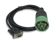
Option: 9-Pin Deutsch to DB9 Connection Cable
Cable is not included in scope of delivery.
PGN 65267 - GPS Data
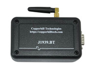
The jCOM.J1939.GPS device connects to an SAE J1939 network and reports the vehicle position (PGN 65267 - Latitude & Longitude) with a one-second frequency, according to the SAE J1939-71 Standard.
The integrated J1939 protocol stack automatically negotiates a node address in the range of 128 to 247. The GPS data is broadcast by using the global destination address (255 = 0xFF). The device's firmware can be updated on-site per the integrated RS232 port, which also allows the loading of customer-specific features.
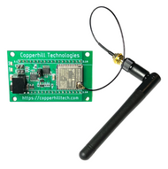
The content of delivery includes the jCOM.J1939.GPS module and the GPS antenna (preferred installation location is the driver cabin, i.e. close to the wind shield).
PGN 65254 - Time & Date, PGN 65256 - Vehicle Speed & Direction
The jCOM.J1939.GPS device responds to requests for Time & Date (PGN 65254) and delivers Vehicle Direction & Speed (PGN 65256) at a 1-second interval.
Note: The vehicle speed is calculated from the GPS sensor reading and may not be available immediately after the power-up cycle. The internal GPS sensor needs to acquire a sufficient number of satellites before the vehicle speed can be calculated. That process will take roughly 30 seconds in average, mostly depending on location and weather conditions. That may also include intermittent interruptions during vehicle operation.
User Manual
For more detailed information on the Parameter Group Numbergs (PGN) for vehicle position, speed, and direction as well as time & date, see the information below.
Features
- ARM Cortex-M3 Processor
- CAN Bus Interface - Fully ISO-11898 Compliant
- RS232 Interface For On-Site Firmware Upload and/or Gateway Functionality
- GPS module with external antenna
- SAE J1939 Protocol Stack
- Extended Temperature Range of -40C to +85C
- Input Power Range of 7 VDC to 36 VDC
- Flame Retardant ABS Enclosure 4.25 x 3.00 x 1.38 in / 107.95 x 76.20 x 35.05 mm
- Environmentally friendly, RoHS compliant
Specifications
- CAN Interface
- CAN Bus Controller integrated in microcontroller
- Fully ISO 11898-compliant
- Supports CAN 2.0A And CAN 2.0B
- Bit rate detection 250/500 kBaud
- GPS
- Receiver type: 56 channels, GPS L1(1575.42Mhz) C/A code, SBAS:WAAS/EGNOS/MSAS
- Horizontal position accuracy: 2.5mCEP
- Navigation update rate:5 Hz maximum (1HZ default)
- Capture time: Cold start: 27s (fastest);Hot start: 1s
- SAE J1939 Protocol Stack
- Fully compliant to SAE J1939/21, SAE J1939/81 and SAE J1939/16
- Sending and receiving of messages (PGNs)
- Message filtering
- Request message processing
- BAM and CM transport protocol (TP) processing
- Static and arbitrary address claim
- Automatic CAN baud rate detection (250/500 kbit/sec)
Please feel free to contact us, in case you need any additional or modified functionality. We can provide solutions within shortest time, and we don't charge when the modifications are minor or help to improve our product.
Automatic CAN Baud Rate Detection
The JCOM.J1939.GPS device provides automatic CAN Bus baud rate detection according to SAE J1939-16 Automatic Baud Rate Detection Process, which requires some special attention when connecting the device to a network. For more information see our post:
- How CAN Bus Automatic Baudrate Detection Works And What To Consider When Connecting To A Network...
- SAE J1939/16 Automatic Baud Rate Detection Process...
In accordance to SAE J1939-16 Autobaud, the device is considered to be classified as Adjustable Baud Rate PI-ECU (PI = Permanently Installed). The device remains in Silent Mode indefinitely until it detects a valid J1939 data frame.
Address Claim & NAME Setting
The NAME used for address claiming does currently not include a manufacturer code. In fact, the device is using a NAME that avoids any interference with the J1939 network, i.e. in case of an address conflict our device will always yield. The jCOM.J1939.GPS will negotiate an address between 128 and 247 with a preferred address of 128.
PGN 65267 - Vehicle Position
The output of the application is PGN 65267 (0xFEF3) according to the SAE J1939-71 standard:
Transmission Rate: 1 s
Data Length: 8 bytes
Default Priority: 6
| Start Position | Length | Parameter Name | SPN |
| 1 - 4 | 4 bytes | Latitude | 584 |
| 5 - 8 | 4 bytes | Longitude | 585 |
SPN 584
Resolution: 10^-7 deg/bit, -210 deg offset
Data Range: -210 to 211.1008122 deg
Operational Range: -210 deg (SOUTH) to 211.1008211 deg (NORTH)
SPN 585
Resolution: 10^-7 deg/bit, -210 deg offset
Data Range: -210 to 211.1008122 deg
Operational Range: -210 deg (WEST) to 211.1008211 deg (EAST)
GPS Data
The image below demonstrates the data output of the GPS module (CAN/J1939 port).
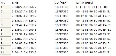
Line 1 documents the address claim. The application is set up for an address range between 128 (0x80) and 247 with a preferred address of 128. The following lines are valid GPS data (pointing to our Windows 10 PC in our office; we moved the board as far as the cable allowed and changes are visible).
Please note that the SAE J1939-71 Standard uses Small Endian for data transmission, meaning LSB comes first, MSB comes last. Also be aware, it might take several minutes after startup before the GPS module can provide a valid position (Once found, it takes only seconds with clear reception). The SAE J1939-71 Standard does not cover such a scenario, i.e. the data output for such a case is not defined. Rather than not sending anything at all, we chose to set all 8 data bytes to 0xFF.
Request Messages
The JCOM.J1939.GPS device reports time & date (PGN 65254) on request.
As the name implies, a Request Message is being used to request data globally or from a specified destination (i.e. node address). The Request message is associated with a specific PGN(PGN 59904) as described below:

The following table demonstrates the use of fields of a Request message type:

Note: For more information on the SAE J1939 protocol in general and Request messages in particular, see A Comprehensible Guide to J1939.
PGN 65254 – Time/Date
Transmission Rate: On Request
Data Length: 8 bytes
Default Priority: 6
| Start Position | Length | Parameter Name | Remark |
| 1 | 1 byte | Seconds | SPN 959 – 0.25 sec per bit |
| 2 | 1 byte | Minutes | SPN 960 |
| 3 | 1 byte | Hours | SPN 961 |
| 4 | 1 byte | Month | SPN 963 |
| 5 | 1 byte | Day | SPN 962 – 0.25 days per bit. Example: 1,2,3,4 = Day 1, 5,6,7,8 = Day 2, etc. |
| 6 | 1 byte | Year | SPN 964 |
| 7 | 1 byte | Local minute offset | SPN 1601 – Always set to 0xFF to indicate UTC (GMT) |
| 8 | 1 byte | Local hour offset | SPN 1602 – Always set to 0xF9 to indicate UTC (GMT) |
Note: The jCOM.J1939.GPS device transmits Greenwich Mean Time (GMT).
Requesting Time/Date
The following image shows a screen shot of our jCOM1939 Monitor software (in combination with our jCOM.J1939 USB hardware) requesting and receiving time & date:

PGN 65256 – Vehicle Speed/Direction
Transmission Rate: 1 second
Data Length: 8 bytes
Default Priority: 6
| Start Position | Length | Parameter Name | Remark |
| 1 | 2 bytes | Compass Bearing | SPN 165 – 1/128 deg per bit |
| 2 | 2 bytes | Navigation-Based Vehicle Speed | SPN 517 – 1/256 km/h per bit |
| 3 | 2 bytes | Pitch | SPN 583 – Not used; Always set to 0xFFFF |
| 4 | 2 bytes | Altitude | SPN 580- Not used; Always set to 0xFFFF |
Firmware Updates
In order to allow on-site firmware updates, we have created a simple Windows program that enables the user to initiate the programming procedure (i.e. switching to FLASH mode).
Note: You will need a USB-to-RS232 adapter to connect the GPS module to your PC. Any standard adapter will do, but we also recommend using a standard straight RS232 cable, since some of these adapters use hex screws that collide with the RS232 port.
Recommended cables:

As shown above, the Windows software serves not only as a firmware updating tool, it also displays the current position, serving as a proof of concept.
Important! Please be aware that you cannot use this unit as a GPS to RS232 gateway. The unit must be connected to a running J1939 network before it starts sending GPS data.
Checking the Firmware and Windows Programming Tool Versions
In order to check the program versions of either the GPS module's firmware or the Windows programming tool (or both), start the Windows program and initiate the connection to the module by clicking on Start COM. Shortly thereafter, the firmware version will be updated on the screen (as shown above using the example "jCOM.J1939.GPS - Firmware Version 1.00.00"). The Windows program version in this example is shown in the upper left corner as "jCOM.GPS - V 1.00.00."
Firmware Versions
CAN Bus Termination Resistor
The jCOM.J1939 comes per default with a 120 Ohm termination resistor activated. To deactivate the resistor, open the enclosure and locate the DIP switch as indicated in the following image.

Serial Interfaces

Details of the RS232 and CAN ports are described below.
RS232

RTS and CTS are not connected. CTS is always held in the ready state.
CAN Port
The CAN port has an on-board 120Ω (0.5W) termination resistor. This termination resistor can be connected or disconnected via an on-board slide switch.

SAE J1939 9pin Cable to DB9 Female
- Compatible with Deutsch Connector P/N HD19-9-1939SE
- RoHS Compliant
- Shielded
- 20 AWG
- Length: 6ft
- All 9 pins connected
- SAE J1939 or SAE J1708 cable
- The open end is perfect for custom cable designs and prototyping
- Heavy-duty materials and quality craftsmanship give the cable superior flexibility and durability
- Order here...
J1939 Connector Pinout

Pin A – Battery (-)
Pin B – Battery (+)
Pin C – CAN_H
Pin D – CAN_L
Pin E – CAN_SHLD
Pin F – SAE J1708 (+)
Pin G – SAE J1708 (-)
Pin H – Proprietary OEM Use or Implement Bus CAN_H
Pin J - Proprietary OEM Use or Implement Bus CAN_L
For more detailed information on the connector and its wiring, please refer to the official SAE document.
J1939 to DB9 Connector Pinout

Note: Pin A is also connected to pin 3 on the DB9 Female Connector.
SAE J1939/13 - Off-Board Diagnostic Connector
J1939/13 defines a standard connector for diagnostic purpose. It does allow access to the vehicle communication links. The connector is a Deutsch HD10 - 9 – 1939 (9 pins, round connector).
According to the official document, SAE J1939/13 Off-Board Diagnostics Connector, the connector supports both the twisted shielded pair media (as defined in SAE J1939/11) as well as the twisted unshielded quad media (as defined by ISO 11783-2). The designations of the individual signal wires are according to the CAN Standard CAN_H and CAN_L. For SAE J1939/11, a third connection for the termination of the shield is denoted by CAN_SHLD.
More Resources

GPS Declassified
GPS Declassified examines the development of GPS from its secret, cold war military roots to its emergence as a worldwide consumer industry. Drawing on previously unexplored documents, the authors examine how military rivalries influenced the creation of GPS and shaped public perceptions about its origin. Since the United States’ first program to launch a satellite in the late 1950s, the nation has pursued dual paths into space—one military and secret, the other scientific and public. Among the many commercial spinoffs this approach has produced, GPS arguably boasts the most significant impact on our daily lives.
Told by a son of a navy insider—whose work helped lay the foundations for the system—and a science and technology journalist, the story chronicles the research and technological advances required for the development of GPS. The authors peek behind the scenes at pivotal events in GPS history. They note how the technology moved from the laboratory to the battlefield to the dashboard and the smartphone. They raise the specter of how this technology and its surrounding industry affect public policy. There are also insights into how the system works and how it fits into a long history of advances in navigation tie into discussions of the myriad applications for GPS.