 Loading... Please wait...
Recent Posts
App Note: Arduino Due With CAN Bus Breakout Board
Posted by on
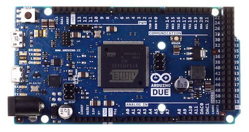
The Arduino Due is a microcontroller board based on the Atmel SAM3X8E ARM Cortex-M3 CPU. It is the first Arduino board based on a 32-bit ARM core microcontroller. It has 54 digital input/output pins (of which 12 can be used as PWM outputs), 12 analog inputs, 4 UARTs (hardware serial ports), a 84 MHz clock, an USB OTG capable connection, 2 DAC (digital to analog), 2 TWI, a power jack, an SPI header, a JTAG header, a reset button and an erase button.
Warning: Unlike most Arduino boards, the Arduino Due board runs at 3.3V. The maximum voltage that the I/O pins can tolerate is 3.3V. Applying voltages higher than 3.3V to any I/O pin could damage the board.
The board contains everything needed to support the microcontroller; simply connect it to a computer with a micro-USB cable or power it with a AC-to-DC adapter or battery to get started. The Due is compatible with all Arduino shields that work at 3.3V and are compliant with the 1.0 Arduino pinout.
For more information on the Arduino Due see: www.arduino.cc

The CAN-Bus breakout board is the perfect solution to adding a full Controller Area Network (CAN) Bus interface to embedded systems such as the Arduino Due or mbed LPC 1768. The board uses Microchip's MCP2551 High Speed CAN Transceiver IC. The output pins are on both screw terminal and DB9 connector. The DB9 can be configure for use with a OBD-II cable or standard CAN pin-out via solder bridges.
More Information on the CAN Bus breakout board...
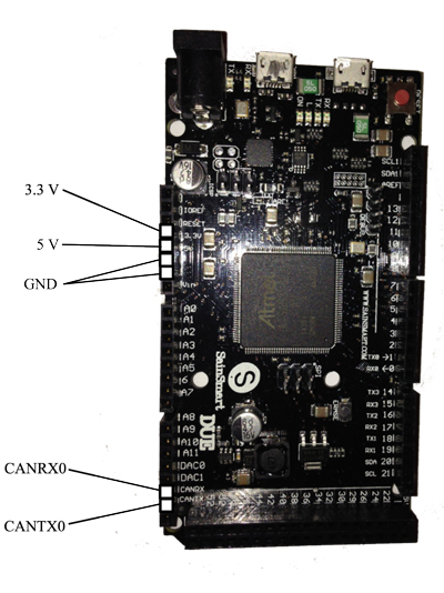
The following image shows the necessary signals on the Arduino Due that are to be connected to the CAN breakout board such as CANRX, CANTX and power.
Note: The usual way to connect a microprocessor board with the CAN breakout board is to cross the Tx and Rx signals. In this particular configuration, the setup worked only without crossing the signals. This is either a general design flaw on the Arduino Due or a flaw by the manufacturer of the Due board (SaintSmart). We have accomplished similar setups with other systems (e.g. mbed LPC1768) where crossing the signals is the standard. Our advice is to initially go without crossing but change it in case the CAN bus communication does not work.
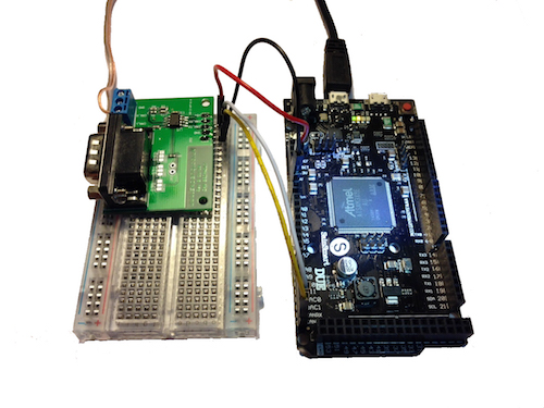
The following image shows the final configuration with the Arduino Due, a bread board, and the CAN bus breakout board.
Programming Resources:
Arduino Due Resources:
- Getting started with the Arduino Due
- Download the Aruino Software (IDE)
- Atmel 11057 32-bit Cortex-M3 Microcontroller SAM3X/SAM3A Datasheet (PDF...)
Programming Arduino Getting Started with Sketches
by Simon Monk
 Clear, easy-to-follow examples show you how to program Arduino with ease! "Programming Arduino: Getting Started with Sketches" helps you understand the software side of Arduino and explains how to write well-crafted Sketches (the name given to Arduino programs) using the C language of Arduino. This practical guide offers an unintimidating, concise approach for non-programmers that will get you up and running right away.
Programming Arduino: Getting Started with Sketches explains basic concepts and syntax of C with simple language and clear examples designed for absolute beginners - no prior knowledge of programming is required. It leads you from basic through to advanced C programming concepts and features dozens of specific examples that illustrate concepts and can be used as-is or modified to suit your purposes.
- All code from the book is available for download.
- Helps you develop working Sketches quickly.
Coverage includes: C Language Basics; Functions; Arrays, Strings; Input / Output; Standard Library Goodies; Storage; LCD Displays; Programming for the Web; Program Design; C++ and Library Writing